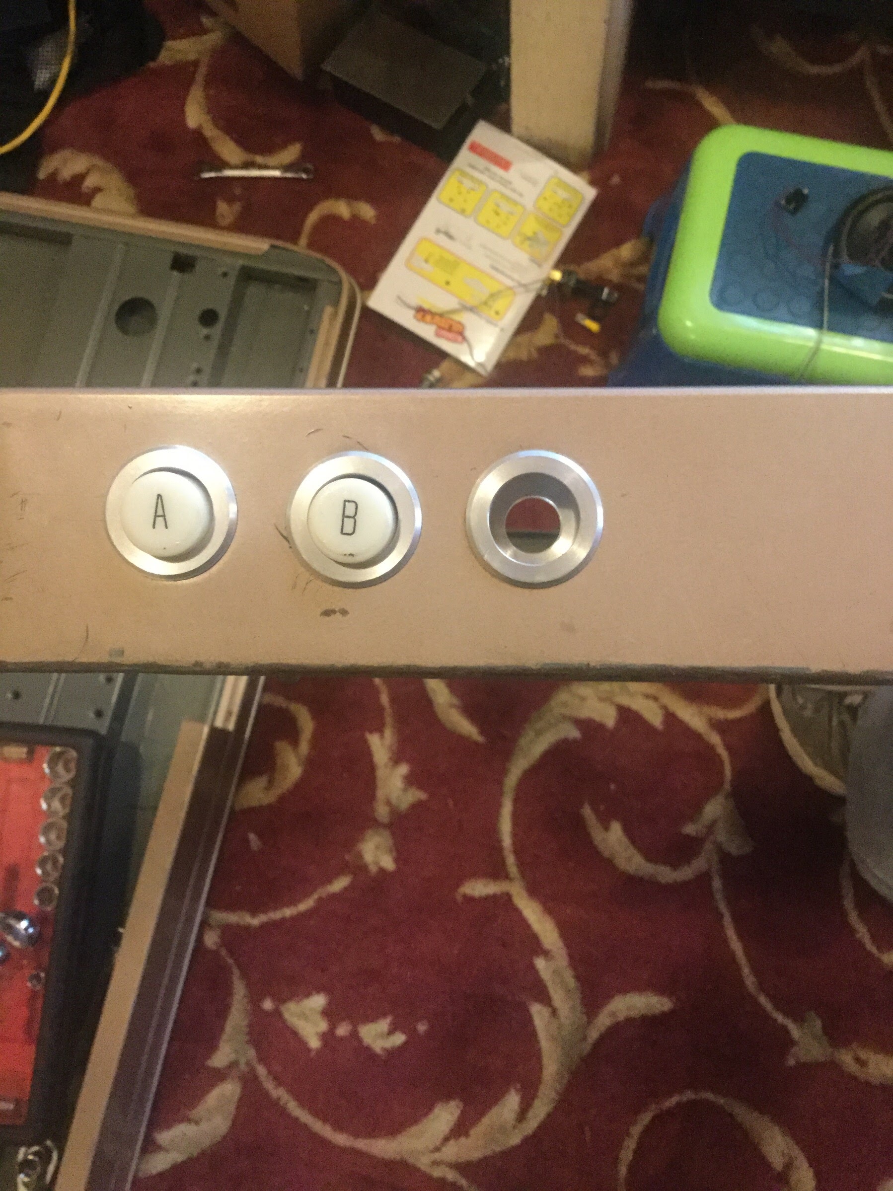
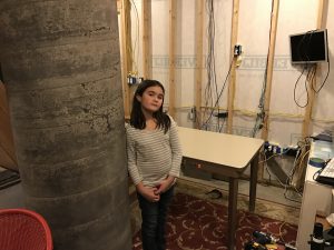
I really like the observatory desk. It’s of a postwar-era “built like a tank” style that has always appealed to me, and the buttons and circuit board were 😮 (have I posted those on the blog? I’ll have to check)
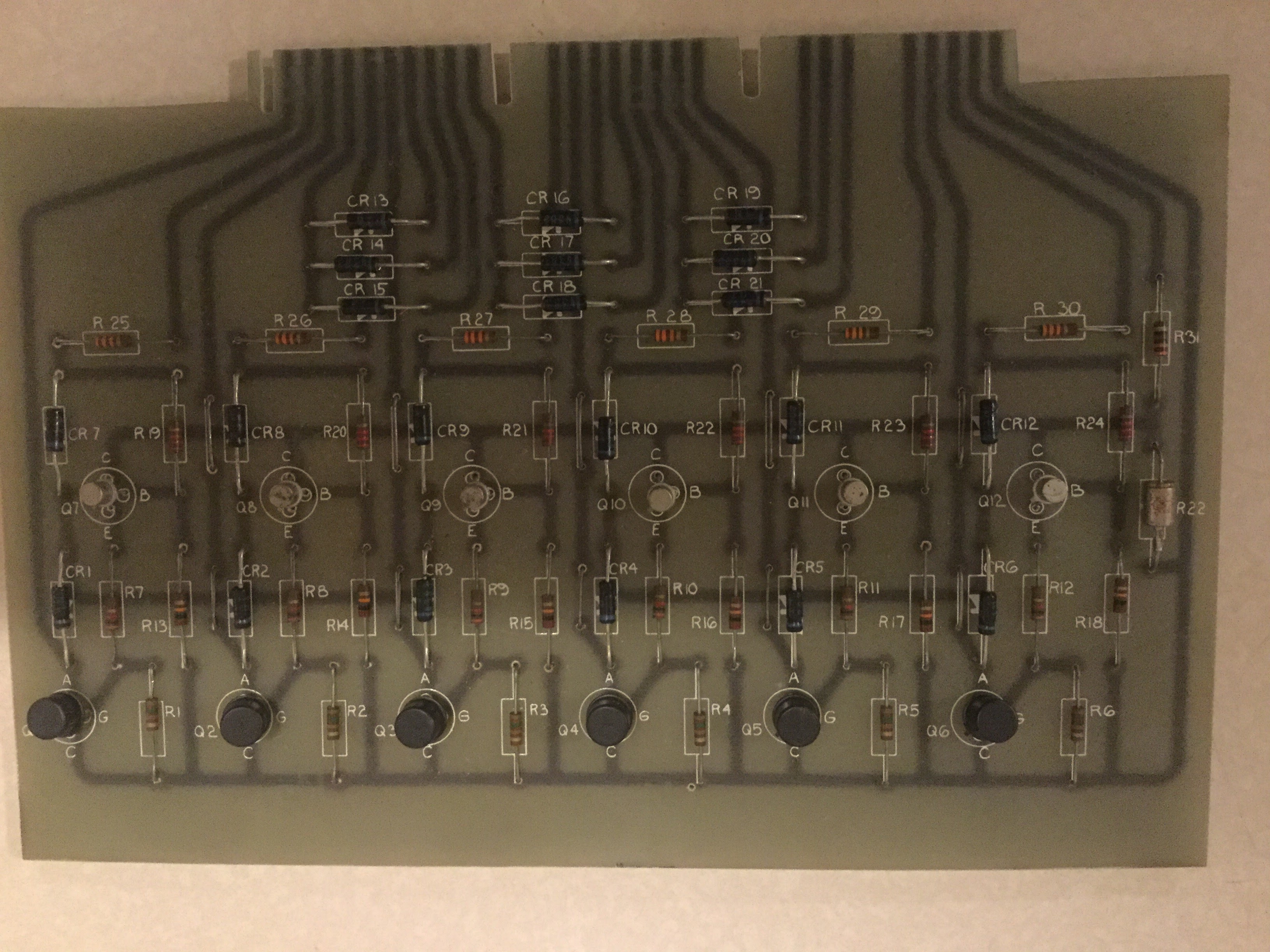
I had planned to use all the original circuitry to wire up to the observatory, because the vintage buttons are too cool and resurrecting an old circuit seems like fun, but what with one thing and another, I decided to replace the wiring and buttons, and get on with the project.
I tried picking up buttons at Vetco, but with the requirement that they work in the existing holes &c, it was easier to just order them off of Digikey instead. I finally picked up a set of deep sockets, been needing some for years, and that was the only way to get the button housings out.
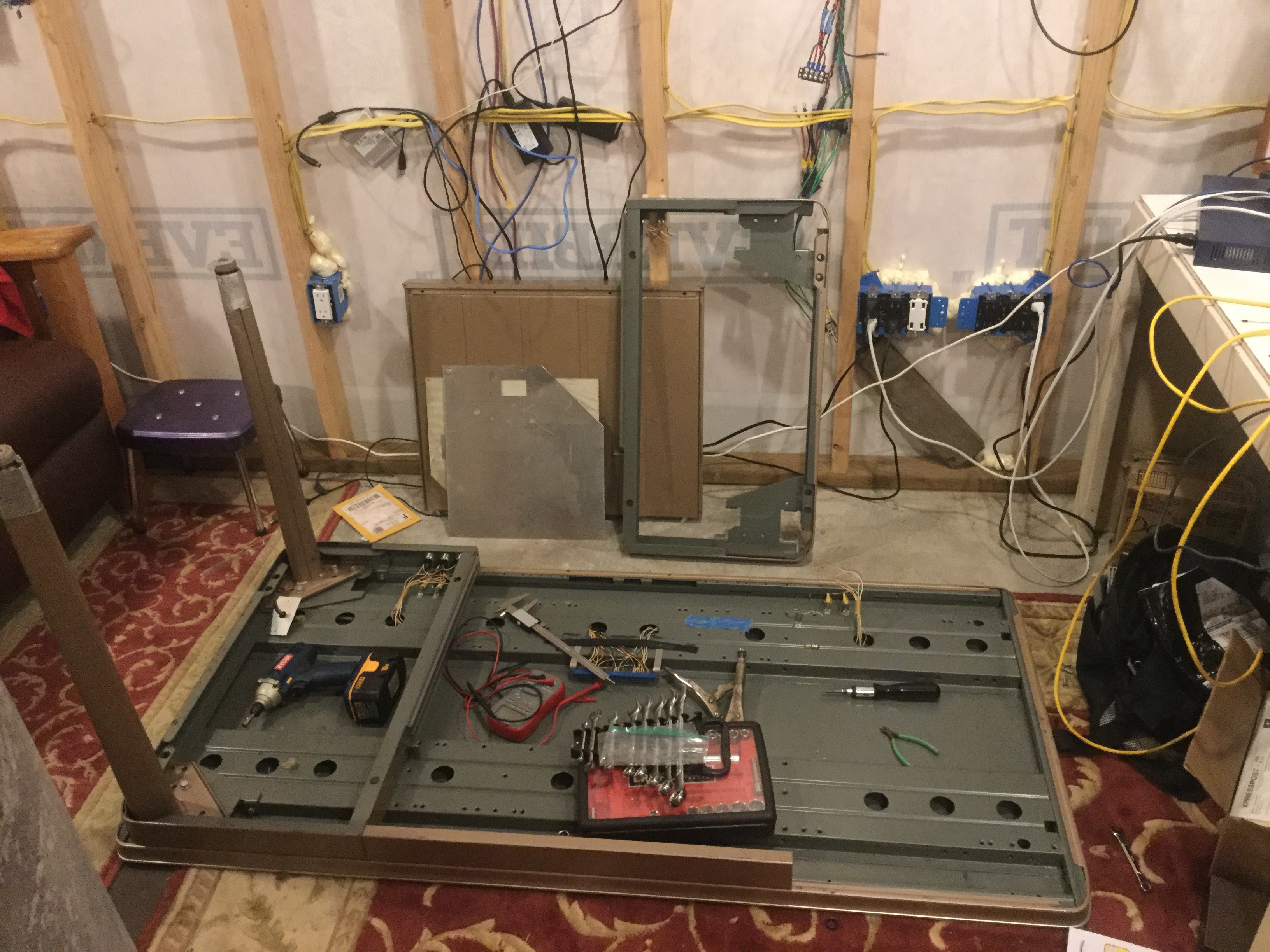
Doing a lot of shipping around Christmas gets exciting, but the extra few days of wait time gave me a chance to prep the desk
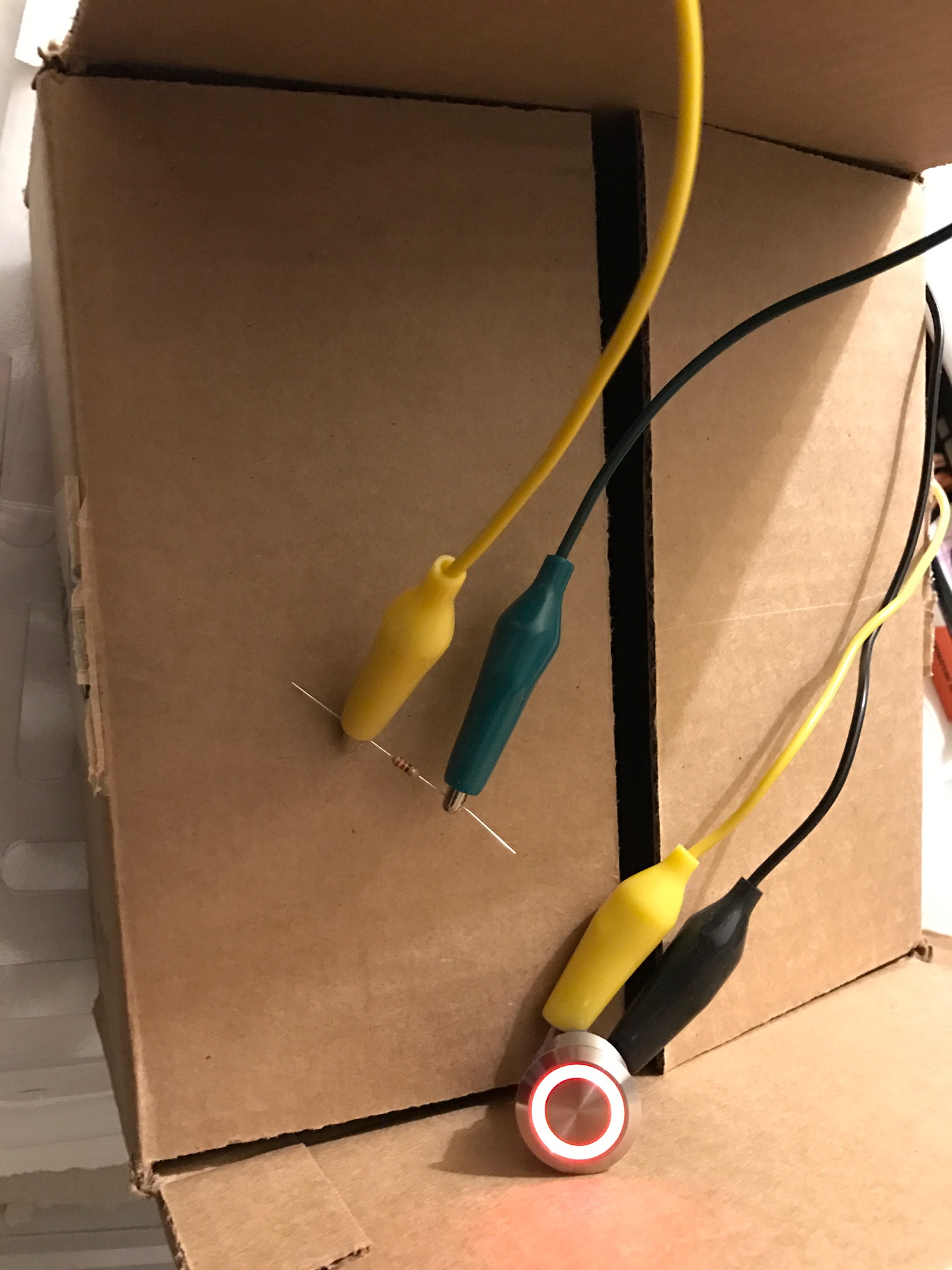
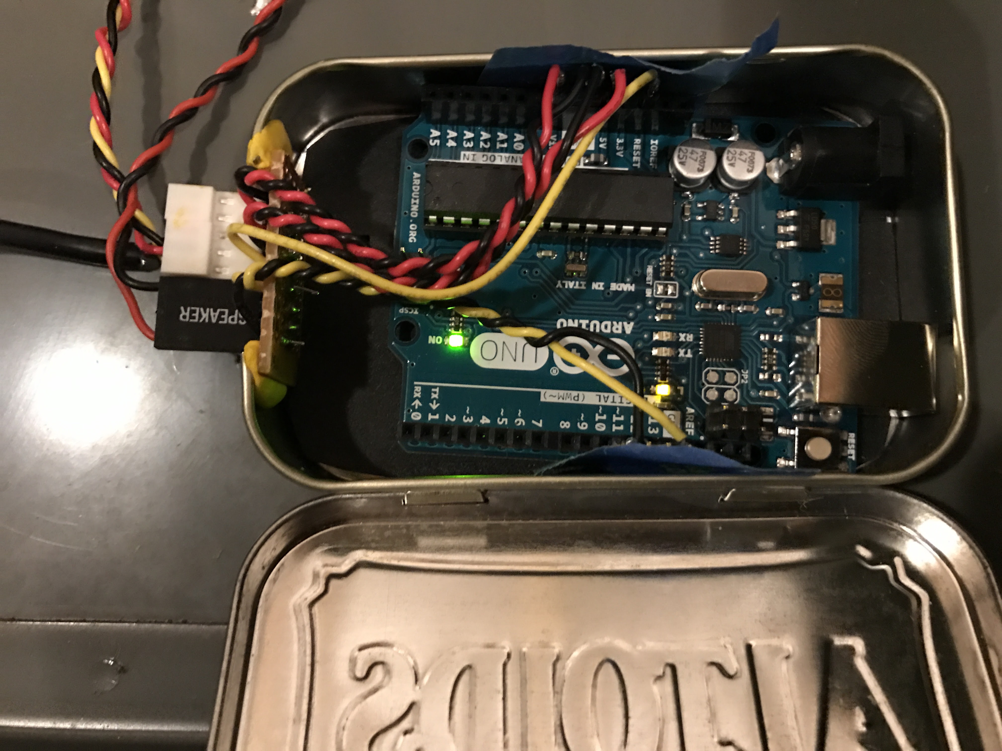
and start working on the first circuit to go in, the motto button. The concept is pretty straightforward; you need: an Arduino, a small speaker, a 5v power supply, and a button. I ended up requiring one extra 220Ω resistor, because the button is equipped with LED illumination, but I’m getting ahead of myself. You record the sound clip (I used Audacity, very cool, open source, and easy to do my little project with), export to .mp3, then convert the MP3 to PCM (which ends up producing a series of 8-bit values, numbers from 0-255). Load the huge array of numbers directly into the Arduino’s PROGMEM , and, as long as the clip is short enough to fit in memory (4kbyte or smaller), you’re done. The sound that came out of the tiny 8Ω speaker (harvested from an old PC) was pretty quiet, but I was able to amplify it a bit in Audacity, so it’s loud enough, I guess, and I didn’t need to spend any time building an audio amplifier circuit (although I researched them quite a bit).
The Jr. Astronomer insisted that I do a recording as well, so I guess the observatory has two mottoes now. My quote was a bit longer, so I had to record it several times before I could spit it out fast enough to work 🙂
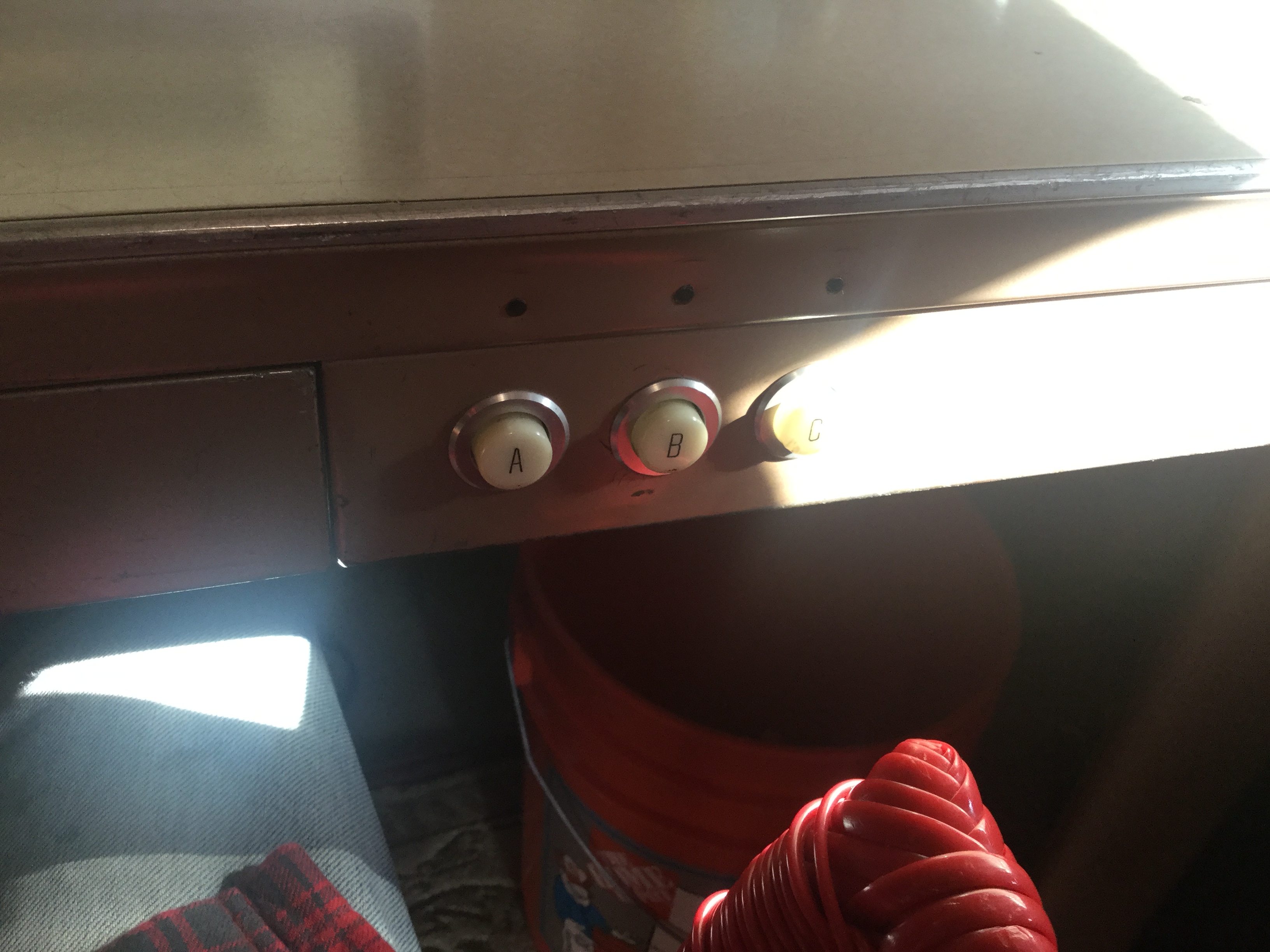
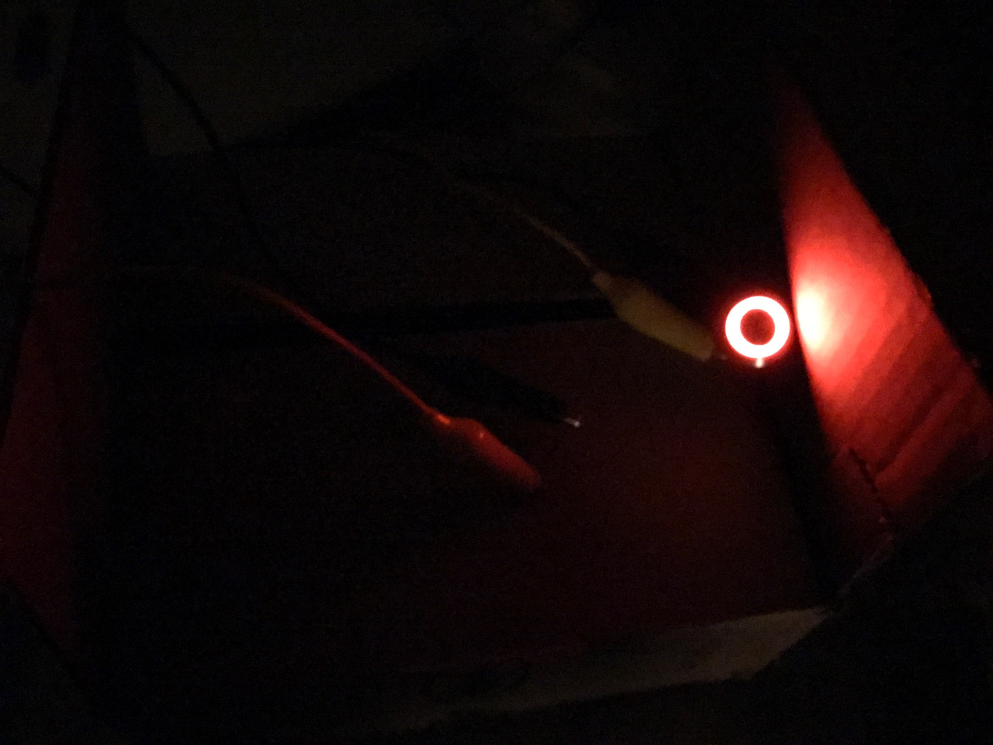
Once the buttons arrived, I marveled at their industrial beauty
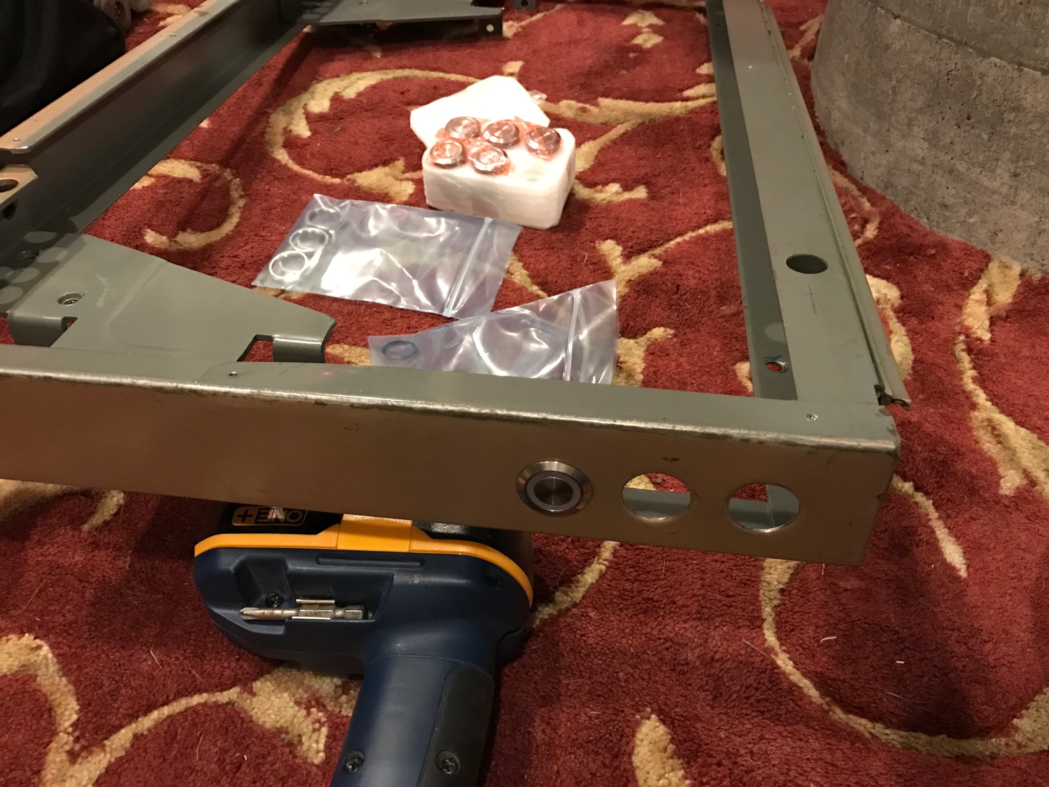
and was pleased to find that they fit without any problems (digital calipers to the rescue!). I spent a little time, making sure that I understood how the LEDs worked (an aside: the diode setting on a DMM will tell you how much forward voltage the LED soaks up, and if you assume 20mA current, you’ve got the resistor value sorted)
Cool, huh?
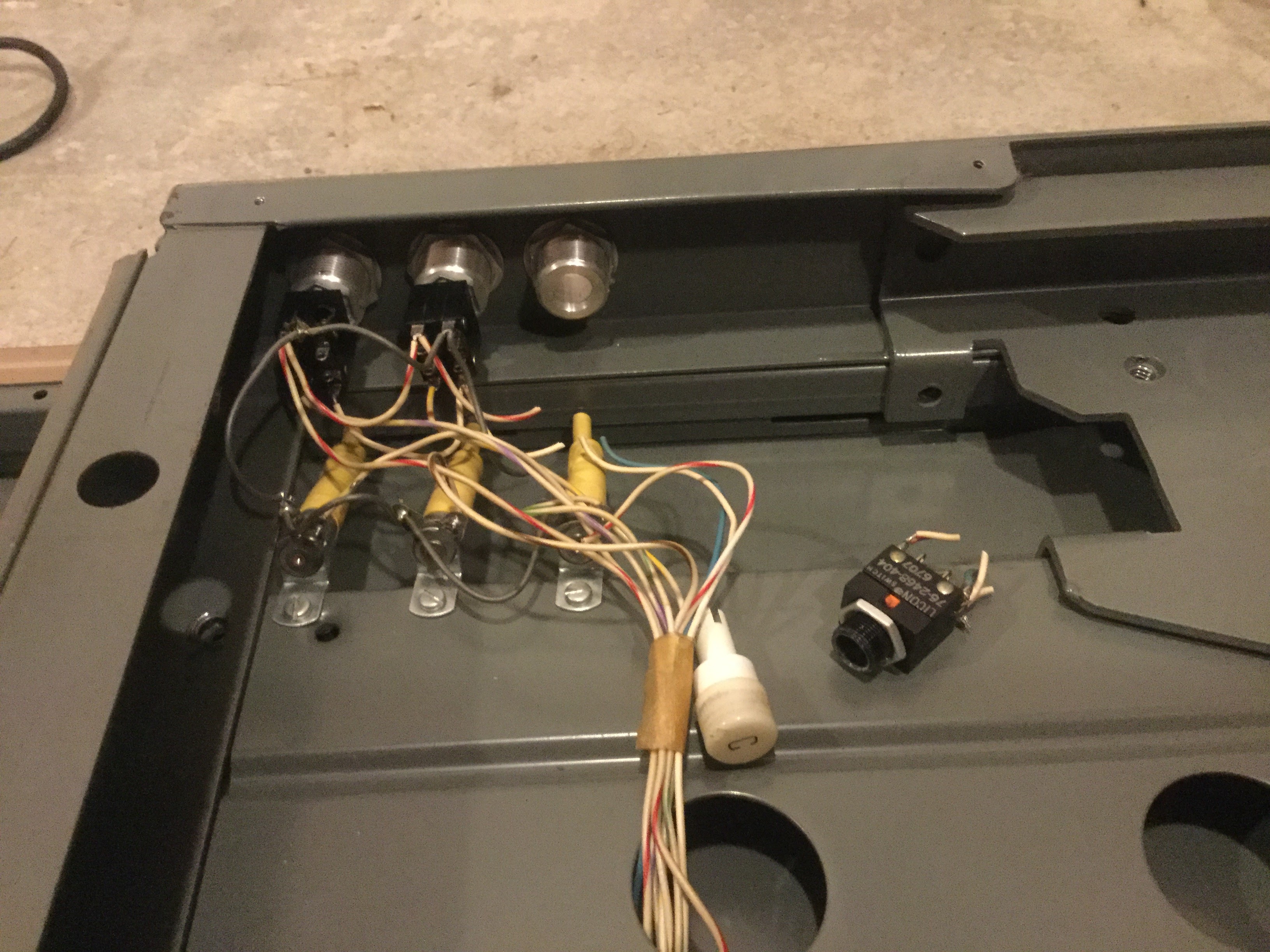
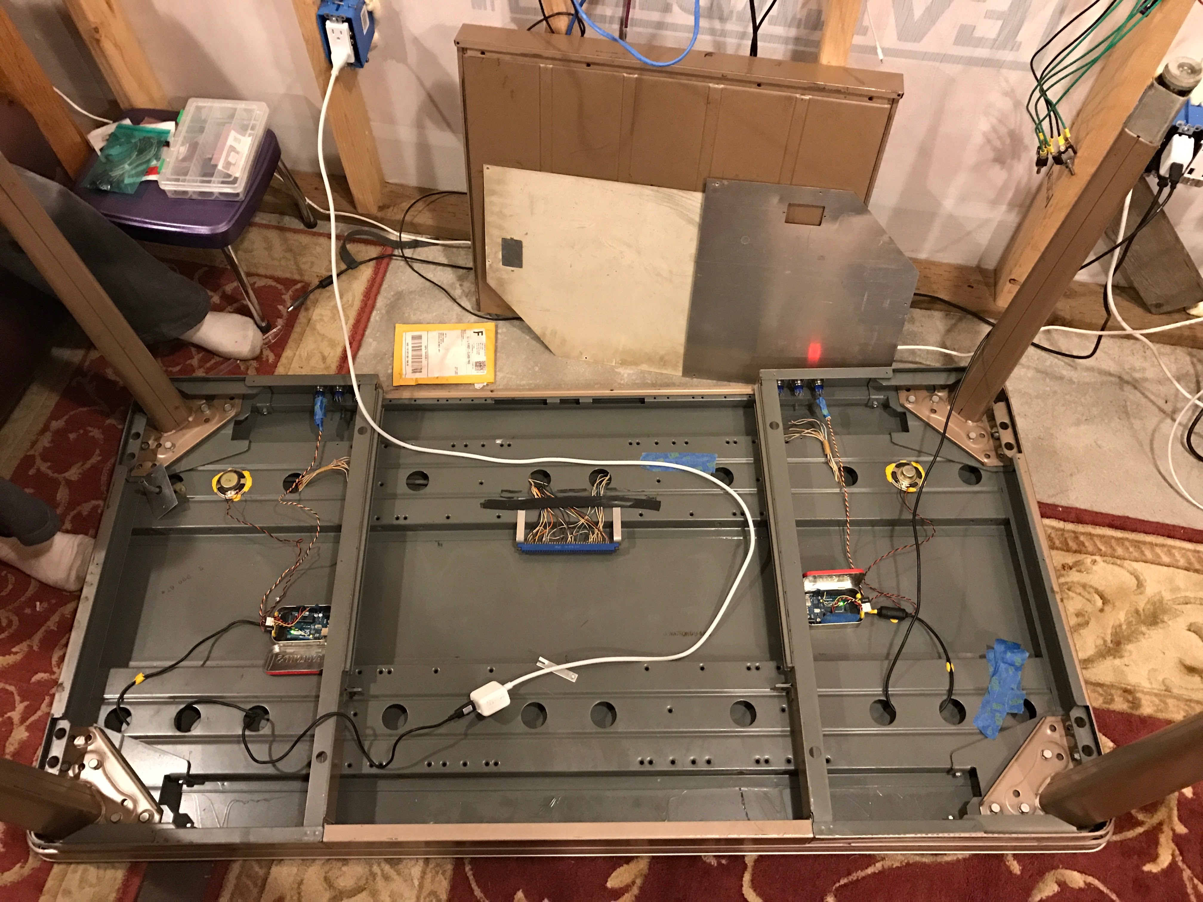
I spent the next day working out how to get everything installed into the desk. Altoids tin, check. Button wiring, check. Everything with connectors, so it can be repaired easily, check.
A small digression, if I may. Wiring connectors always seems to be a huge problem for me. I don’t know why. Every kit you get, the “right” connector is “just there”, and you never think about it, until you’re sitting there, with a button with spade terminals, an Arduino with female 0.1″ sockets, and a bunch of solid-core hookup wire, and you’re thinking to yourself “well, now what?”. I found some connectors on Mouser/Digikey where you shove the insulated wire end into the thing, and it cuts the insulation and grips the wire. I don’t know what they’re called, but they have 0.1″ spacing, and they came in 2, 3, 4, … 10 connector versions, and they fit right next to each other on a row of pins, bonus. I think there’s probably supposed to be some kind of punch-down tool to install them, because the way I’ve always done it (it involves shoving each wire real hard with partly-open needlenose pliers, and hopefully not impaling yourself in the process) just *can’t* be right 🙂 Also, the 2-wire ones (which are super-popular, because + and GND, so I’m almost out of them) seem to be the least consistent as far at making a good connection, and I always end up ruining a couple, and … I’m irritable. I’ve tried “servo” connectors, without a special crimper, those have their own set of problems, not the least of which is that there’s a “correct” way to hook them up…
If someone out on the Internet wants to help me understand which connectors to order, to go between two and five individual 24ga wires, and male 0.1″ header (I need a female connector), I’m all ears.
Back to the show.
So for 5V power, I’m totally ruined by the fact that USB cables (of which you, the reader, have at least 200, sitting around in dusty cabinets and desk drawers, right now, go count, I’ll wait) are an easy source of 5V, and work from the USB port on a computer (or the charger for any mobile phone). Every old piece of proprietary charging equipment I am about to throw away gets its USB cable removed for future projects. In this case, I needed two (one per Arduino).
Sadly, USB cables are often made of really junky, wimpy wires, which makes the life of a maker more difficult.
Between the nearly stabbing myself trying to get the connector to work, and the flimsy wire which required redoing the connector half a dozen times, and of course, not really knowing exactly what I needed to do, to make this whole installation come together, finishing the first button took most of a day.
With the confidence of hindsight, the second button went along much faster. I got it done in half the time, and most of that was helping the Jr. Maker (we got the other kid involved! w00t!) understand how the thing was going to come together.
With both buttons installed and functional, all that remained was to nail everything in place with my very favorite stickum, Sugru.
I would have a nifty photo of the finished product, and perhaps by the time this goes to press, I will, but I was so excited to be making some progress on getting the observatory wiring done, that I just had to post.
Next up, an enclosure for the motor controller. I need to get that done, because until it’s finished, the dome won’t open. 😛
Merry Christmas to all, and to all a good night.
MOST COMMENTED
Observatory
Observatory 2.0 – Time has come today!
General / Maintenance
First Light, a deeper look
Mount / Observatory / Telescope
Observatory 2.0 – Result!
Observatory
Observatory 2.0 – The Pier goes in
Gear / General / Maintenance
Martin Farmer Wormblock installation notes
Deep Sky / Long Exposure Photography
NGC2244, The Rosette Nebula
Deep Sky / Long Exposure Photography
Another beautiful night.