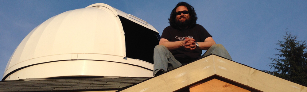

I have skipped a couple of steps, here, so let me first fill you in on what’s been happening with the observatory build. When we last left, the dome had just gotten test-fit together. Since then, a number of things have happened.
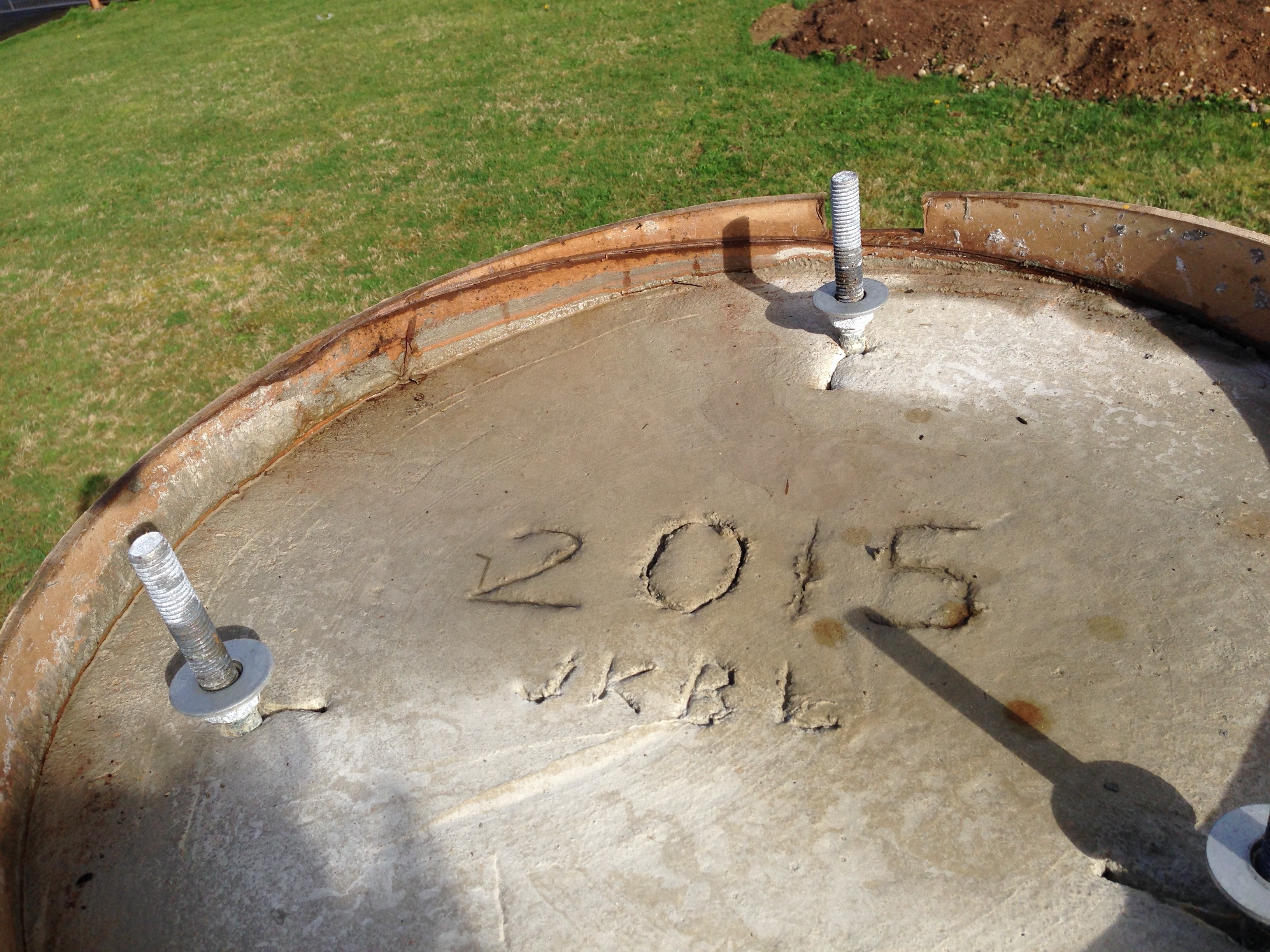
First, the second half of the pad got poured, and there has been plenty of rain to keep it curing nice and slow. Athena is doing a great job, keeping an eye on things out there.
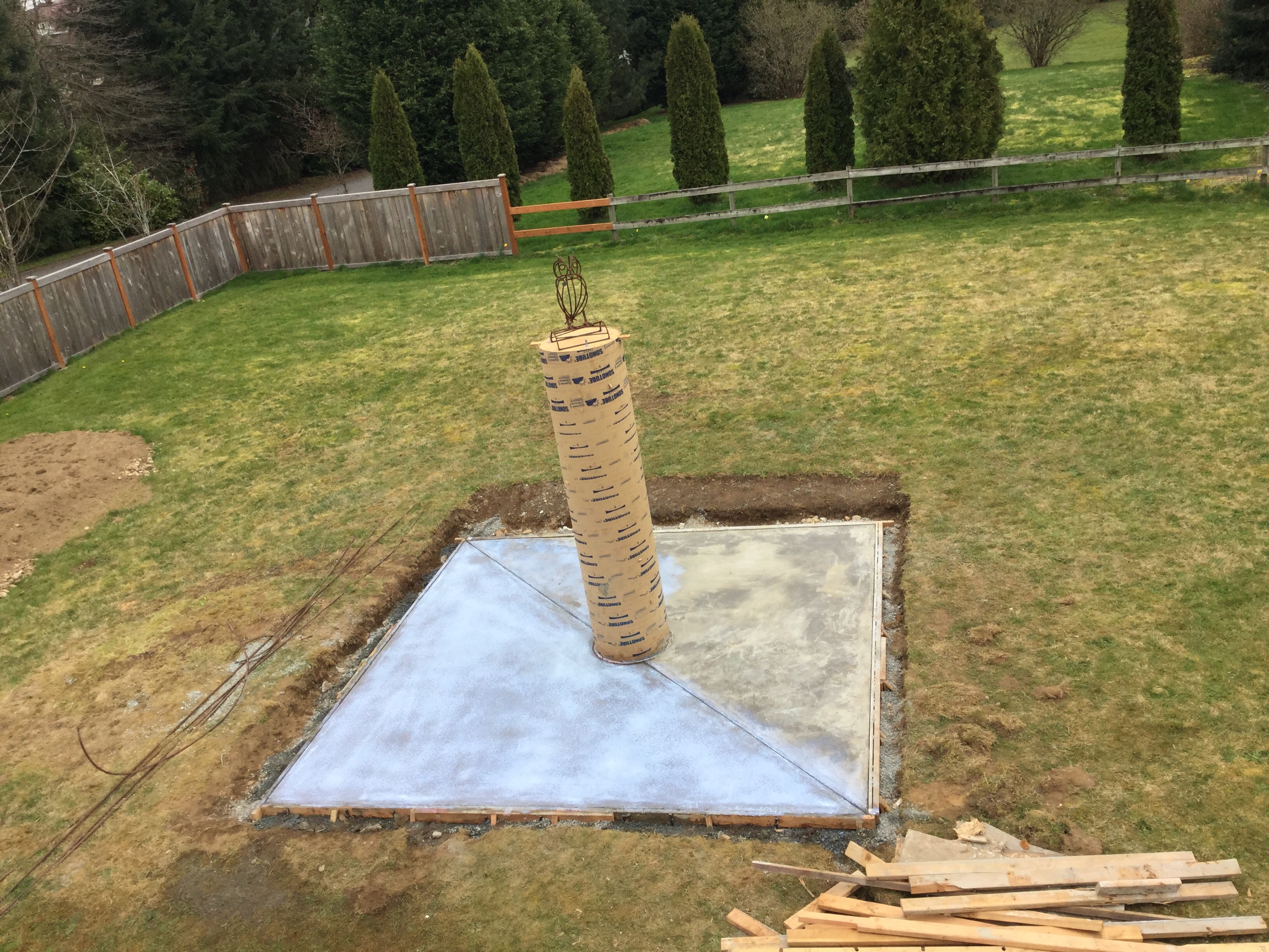
Second, I ordered the steel pier from a local machine shop, Bjorklund Machine Works. Steve has been doing a great job, trying to understand what it is that I am looking for, and I am confident that i will love the pier. The wooden jig that was used to place the J-bolts in the concrete is now at the shop, as are a pair of electrical junction boxes, which will carry the AC, DC, and data ports for the telescope, mount, etc.
Third, I did some hopefully final-ish measurements of Trixie on the tripod, to make sure that I had the ground clearance number correct. So far, I keep getting the same number, and I also know how much adjustment I have in the J-bolts, so that lends confidence.
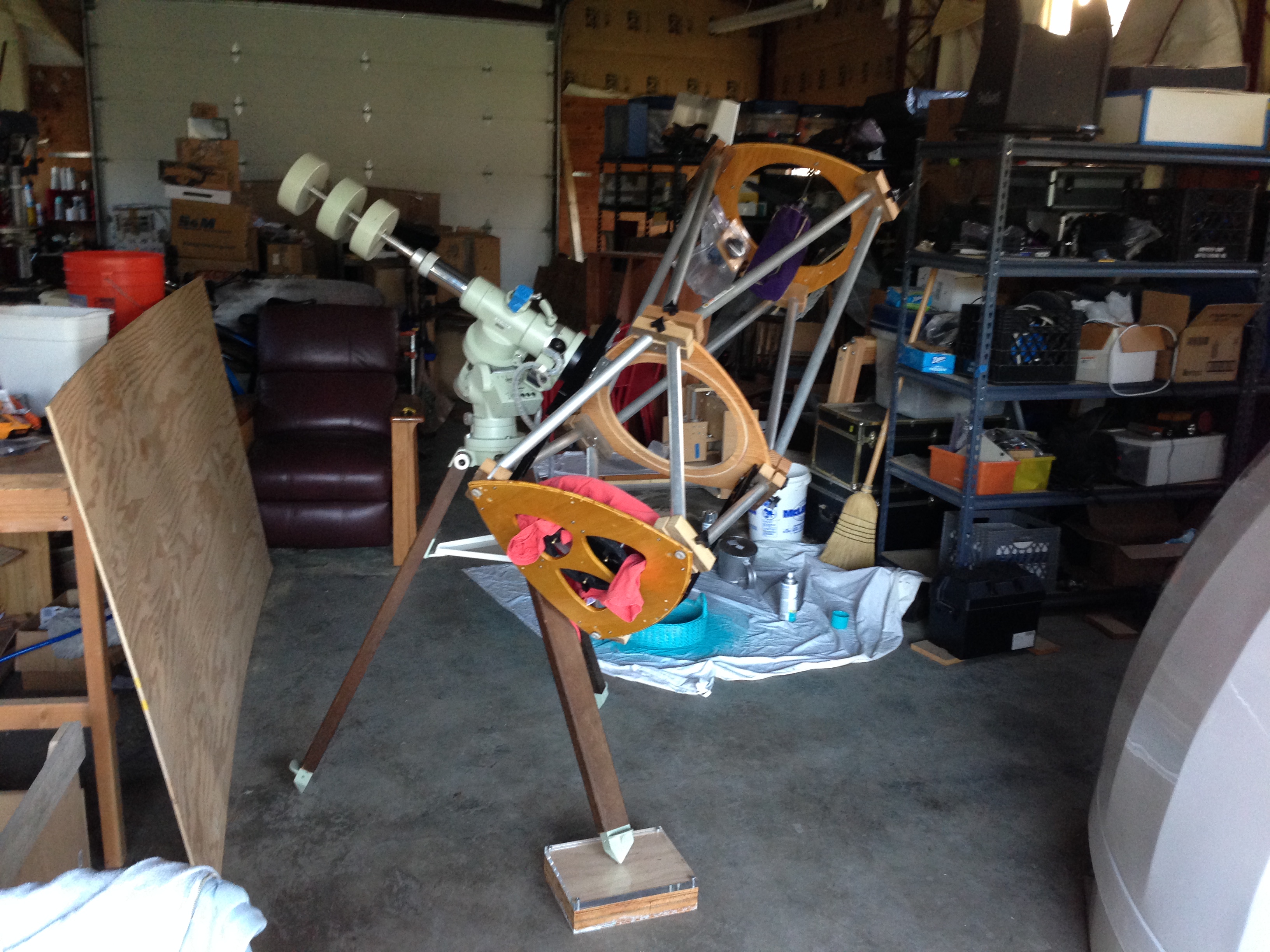
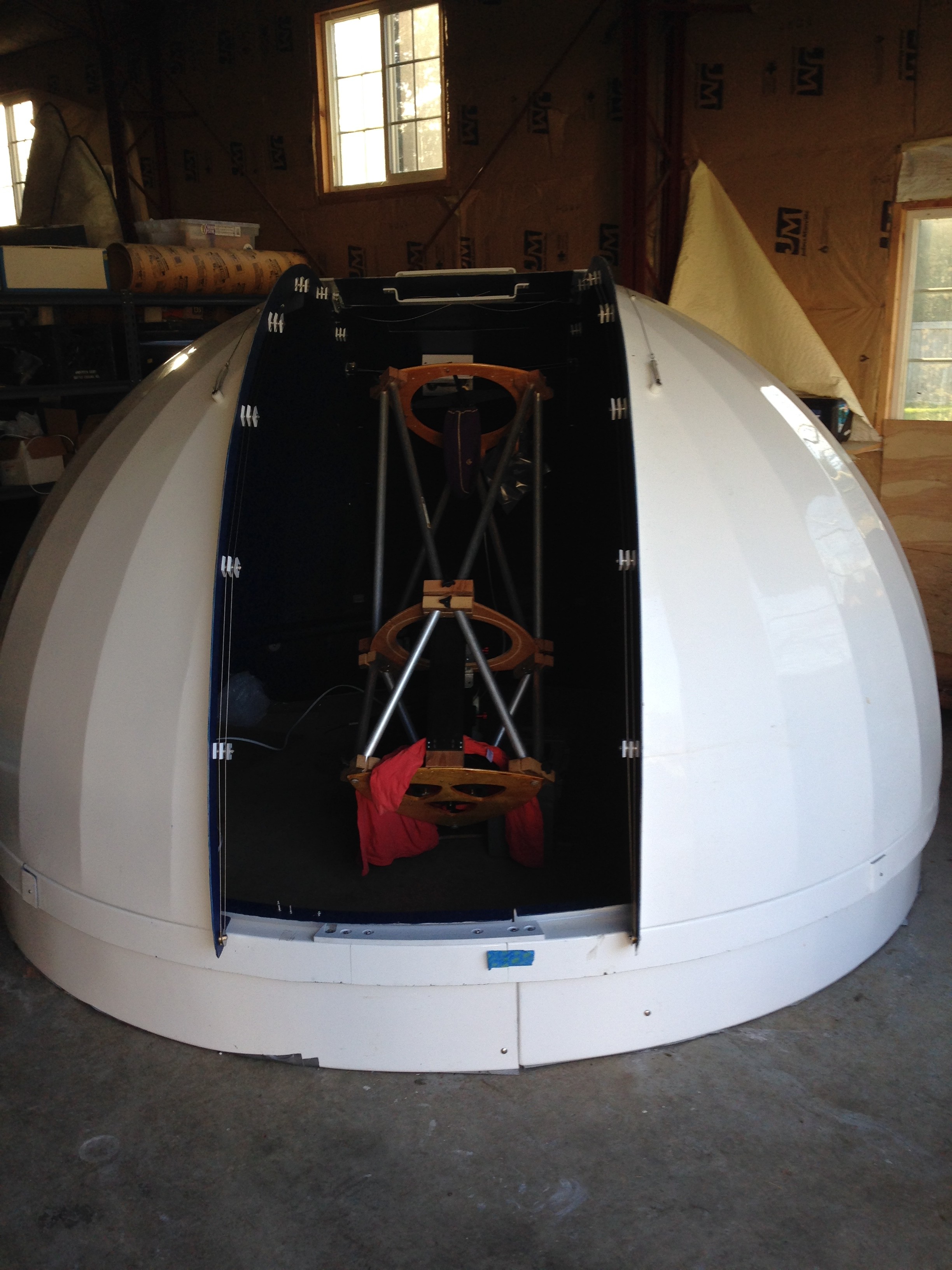
I also test-fit Trixie under the dome for the first time, sitting on the NJP on the floor of the shop, to make sure that the roof clearance was working properly. It is.
Fourth, I picked up some white gelcoat to fix all the dings and gouges on the dome before it gets installed, and K, L and I spent a couple hours cleaning and patching. The resin is still curing, so we shall see how we did tomorrow.
Finally, I ordered, received, and installed the rotation and shutter motors for the dome.
A few test runs show the motors working well. I ordered the motors from the dome manufacturer, to make my life easier. I am glad that I did, because the bracketing is complicated. However, I didn’t buy the power supply / control box from the manufacturer, because I hear theirs is not totally amazing, and because I think my electronics skills are up to the challenge.
Which brings us to what I did this weekend.
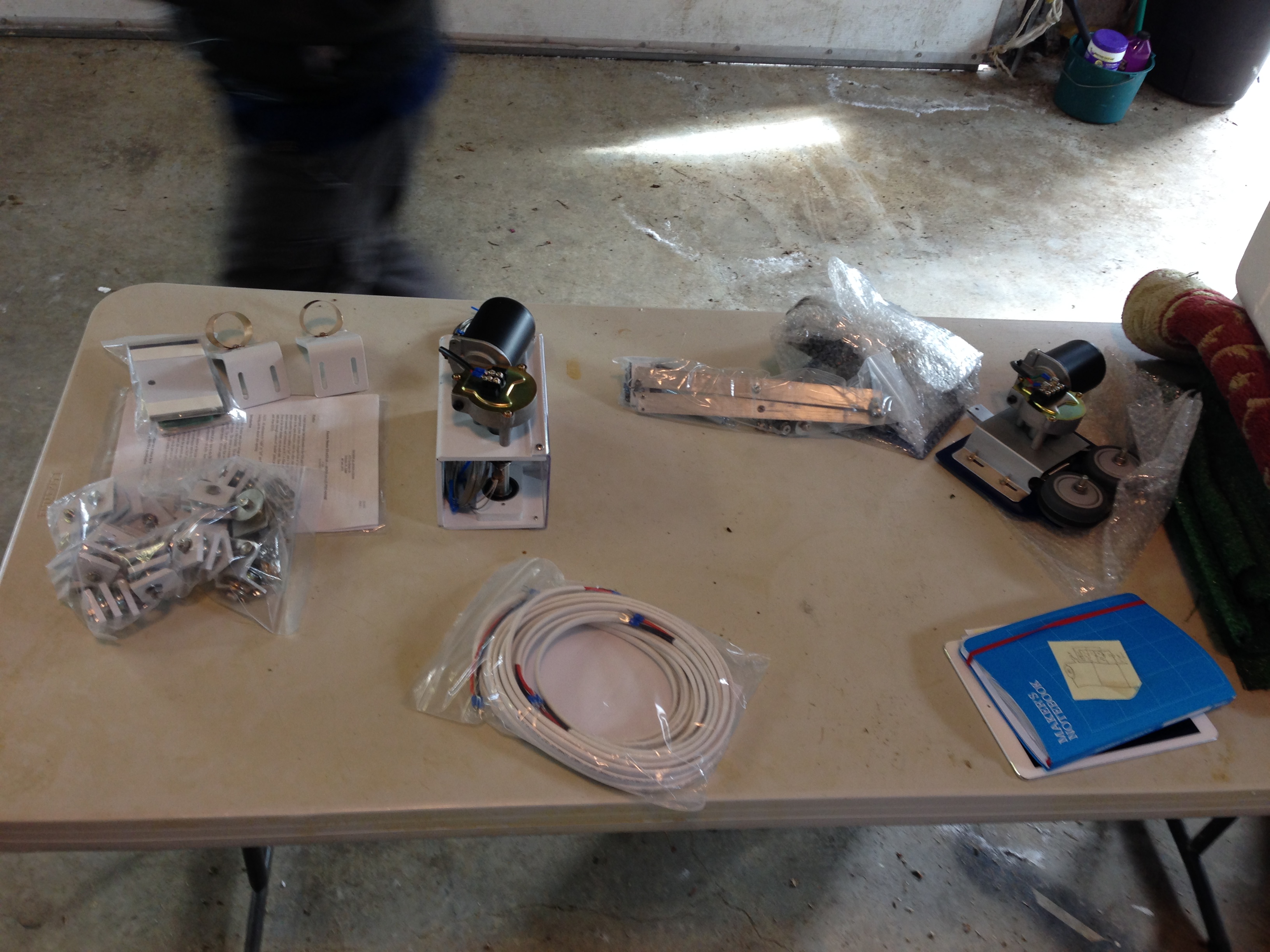
I have been considering LesveDome, a software / DIY hardware dome automation solution. One of the LesveDome users was kind enough to write up a couple of very nice schematics, and I spent many days scratching my head over them, refactoring and making sure that I understood what to do. Then I put in an order with Digikey. Relays, sockets, terminal strips, magnetic limit switches, and some shaft encoders all showed up. Trips to Home Depot and Vetco produced 12 gauge wire, various toggle switches, rectifier diodes, and crimp connectors.
My original design had a DPDT relay wired to switch between a battery charger circuit and the dome circuit. I may still revisit this design in the future, as I feel it has an elegance worth pursuing. However, my first attempt at it caused a 1N4005 diode to let out the “magic smoke”, so I decided that maybe a simple DPDT toggle switch was the order of the day. This part of the design was something that I created in a small wave of hubris, not part of the original LesveDome circuit.
I don’t need full automation at this stage of the game, just some simple switches and battery connectors, so that I can hook up and drive the dome without having to touch wires to the battery terminals.
Even without considering automation, a circuit to reverse a motor is not trivial. Each motor requires two relays, one for “on/off” and the other for direction. Diodes and careful hookup “logic” do the rest. I figured out early that the original relays I bought from Digikey, which are 24v, will not work well with my 13.8v power supply. All those voltage drops from the diodes really killed the power level to the tune of about 1.4v. I suppose that means two diodes, now that I think about it. 🙂 I tried to find 12v relays at Vetco, but relay sockets are fairly specific, and they didn’t have ones that fit in stock. Once I determined that 12v relays will, in fact, solve the problem, I ordered some from Digikey.
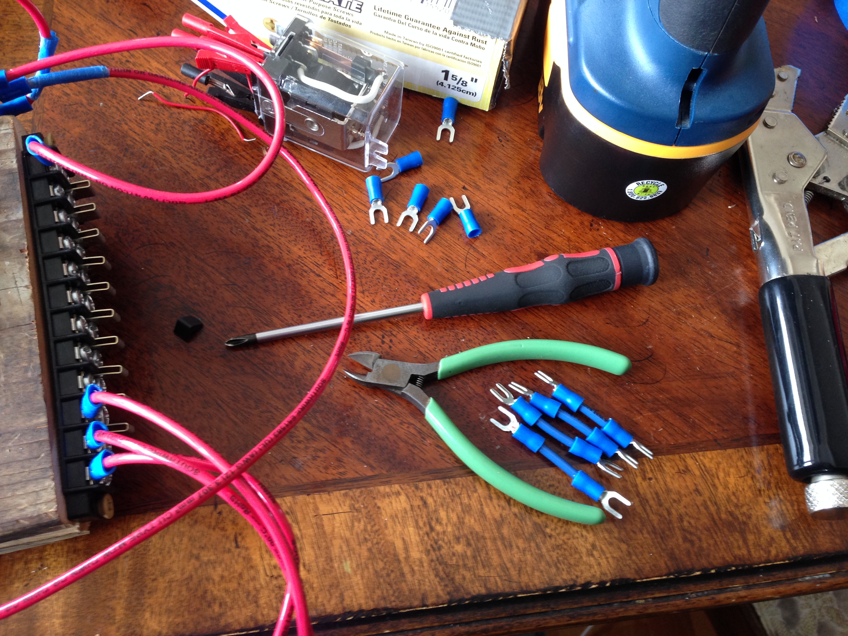
I was able to determine that the rotation circuit should work, given the proper relays, so I made a copy of it for the shutter. Note that the “copy” required over a dozen cables (I counted 14, but I might have missed one), with crimped connectors on each end, plus a handful of diodes thrown in. Add in power, ground, and I/O busses, and quite a bit of “I’ve never done this before”, and it took the better part of two days to complete the build.
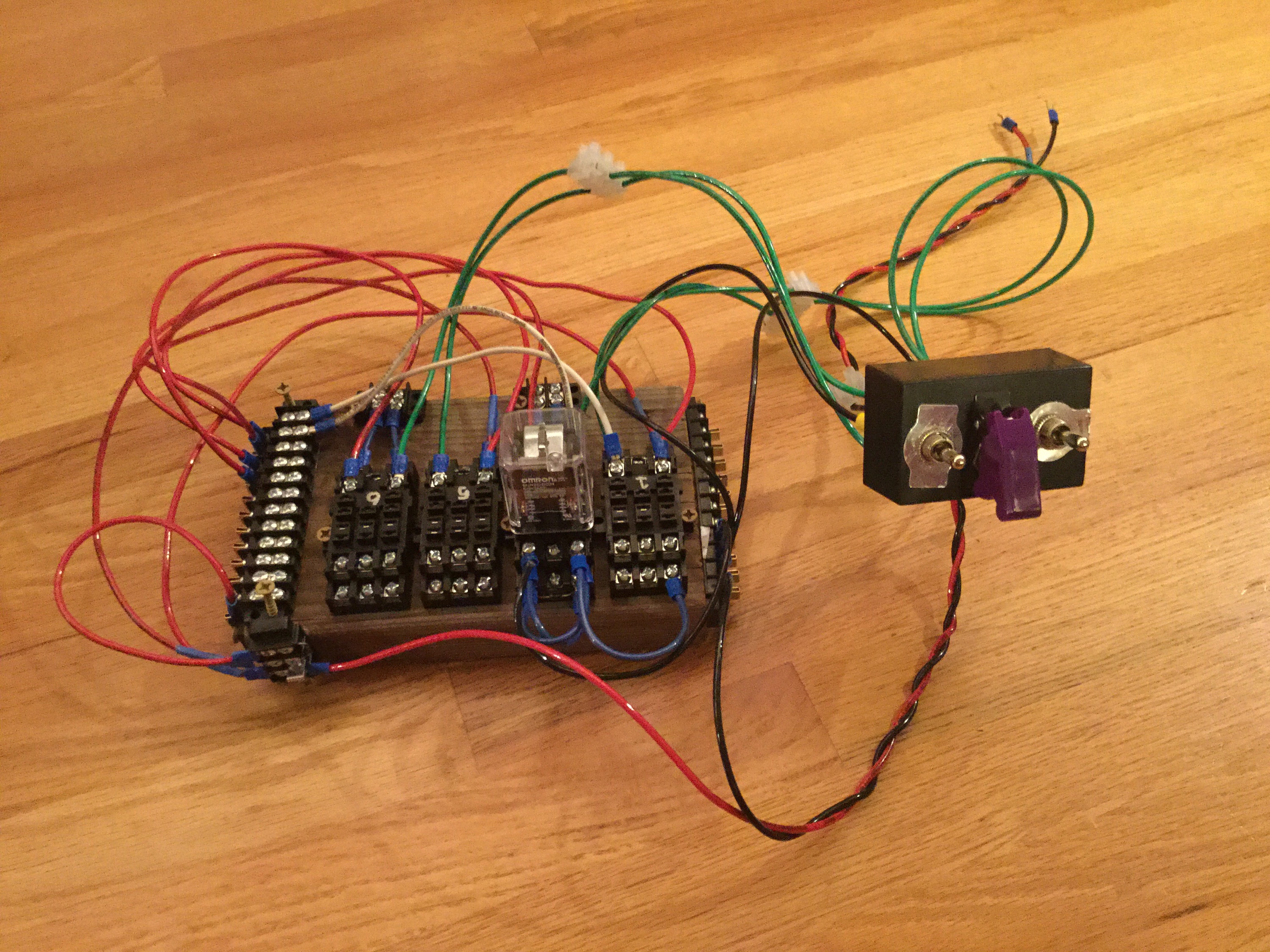
My favorite part of the build was “programming” the relays; there’s a cool little criss-cross thing that I had to do with the “directional” relay that makes me all happy inside. I decided early to color-code the various bits, as well. That really helped me with debugging. In case you’re wondering, or it’s me reading this 5 years from now, red/black (duh), green for “inputs” (switches), blue for “outputs” (motors), white for “data” (from the µC). The directional switches break/make the GND connection, thus all the red wires and so few black ones. Oh, and I blue-coded the motor power wires, which come directly off of Vin, as opposed to the rest of the power bus, which has a flyback diode to Vin.
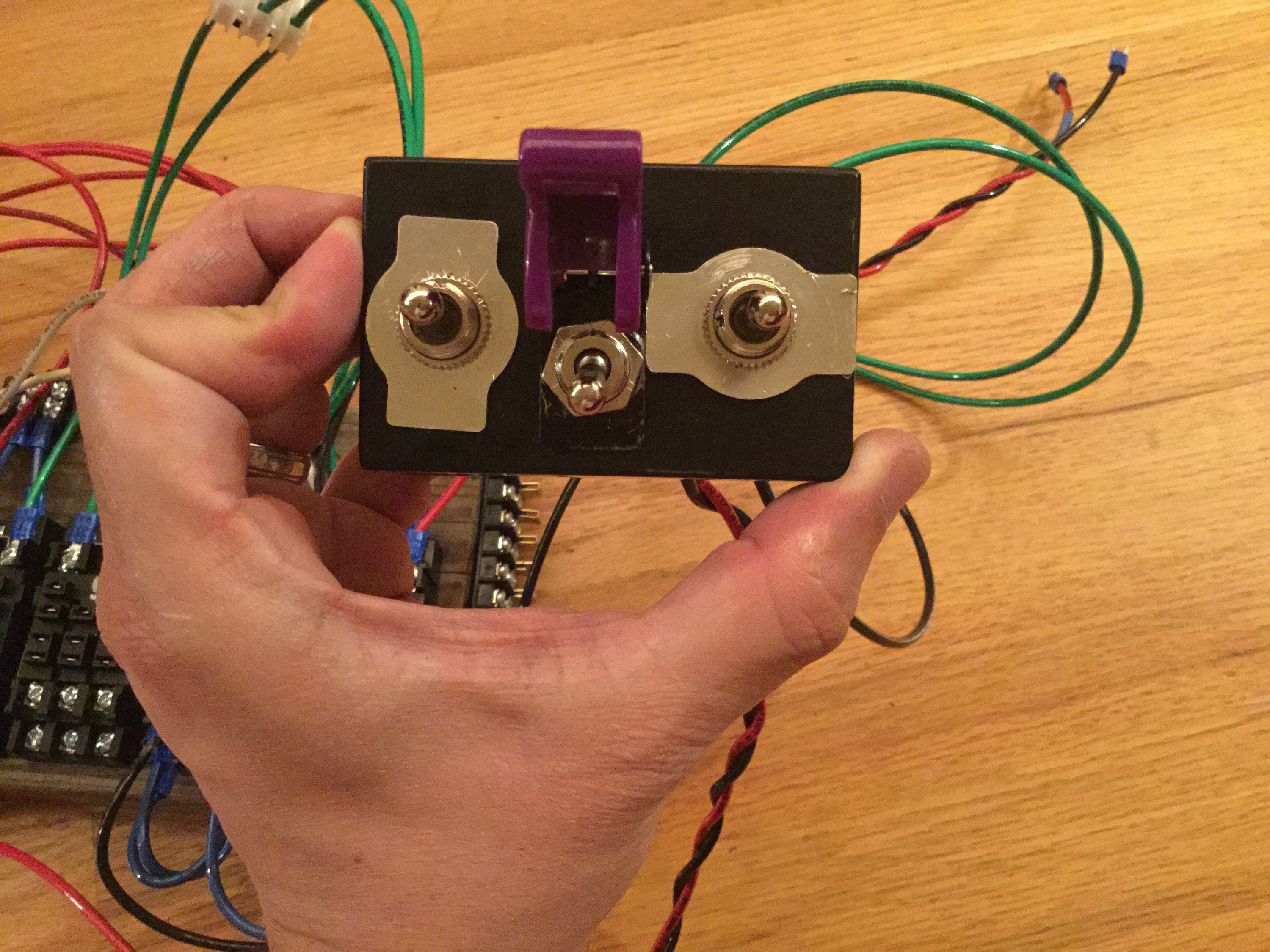
Functions that (should) work right now:
– Dome rotation CW/CCW
– Shutter Open/Close
– Power/Charge switch (complete with “too close for missiles, switching to guns” protective cover B) )
Things I still need to work on:
– “Programming” the shutter relay the same as the rotation relay
– Testing on the dome
Once it’s working well in the dome, I think I’m pretty set for a basic set of dome controls. I hooked everything up with automation in mind, though, so at some point down the line, I can add home sensor, upper and lower limit switches, and the rotation encoder, and of course the microcontroller brain, without reconfiguring any of the circuit. It would be best to put it in a project box, too, if only to protect it from the elements. Yes, I like “2×6 chic” as much as the next guy, but let’s call this “v0.5-beta”.
Even with “basic functionality”, though, I really feel like I took a huge leap toward a working observatory!
Impressive! I love the details,lots over my head,but like to read it all. To think I use to wash your hair in
my kitchen sink!
Wow . Lot of hard work and passion
Lovin it. I hope Athena gets to take a permanent role in the future.