
So, that’s how we do that.
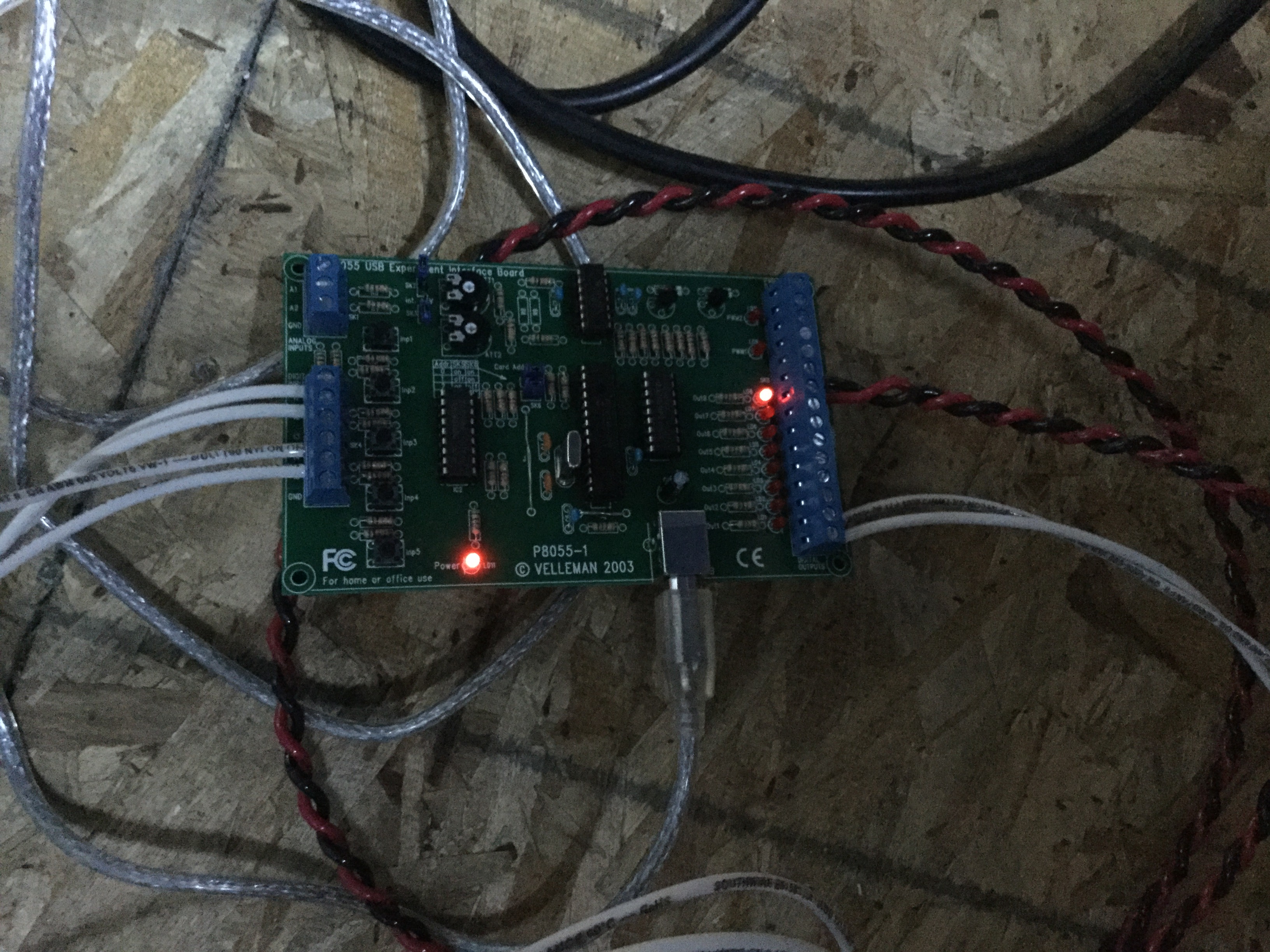
Yesterday, I worked on getting the encoder and home switch cables hooked to the Dome Controller, which I hope you’ll recall is a Velleman K8055 board. I studied the Lesvedome schematics a bit, and decided that for azimuth-only control, I needed to connect just a few wires to the board:
* 12v
* GND
* Inputs 1 and 5 (encoder)
* Input 2 (Home)
* Input 4 (rotation direction CW/CCW)
* Outputs 1 and 2 (rotation)
It sounds like a lot, but after the wacky RJ12 stuff, it seemed pretty straightforward.
Here’s a look at the K8055 with the new wires installed.
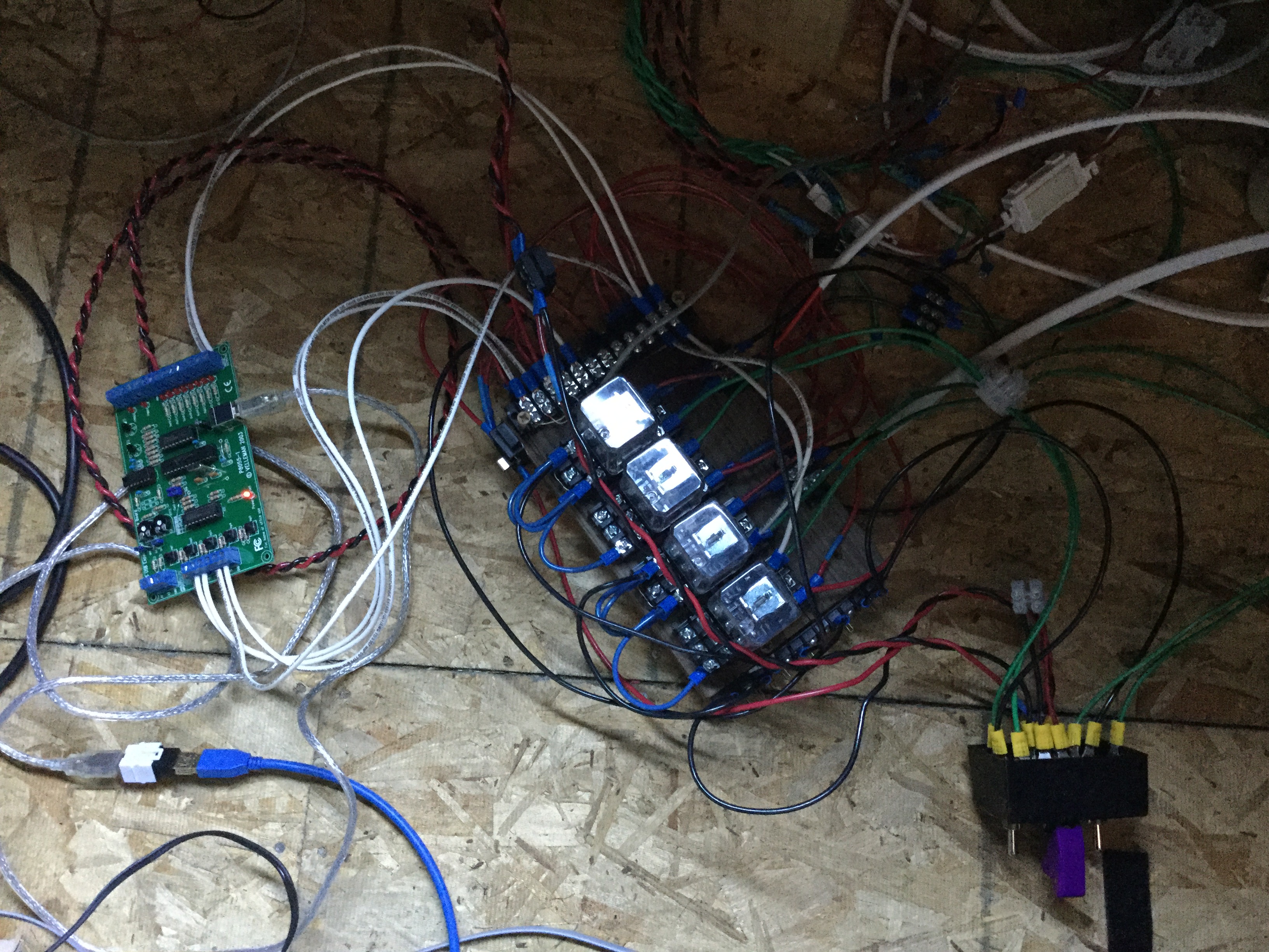
And here’s the whole “dome controller”, with the K8055 board and the relay board I’ve been using for the past year to control the dome manually.
For some reason (to be determined), the K8055 and the status LED circuit that I made, were not playing well together. I tried hooking the LEDs to GND and to Vcc, and neither worked right. I decided to pull the status LED circuit out, and deal with it later. This means that I don’t have a visual cue about dome movement or home position, but I guess that’s another show, again. 😐
I also sent away for a trial key for Lesvedome, the ASCOM Dome driver that I’ve been targeting (and the whole point of the encoder-and-home-switch thing in the first place). The developer turned the key around quickly (thank you!), and so I was ready, this morning, for a first test.
Lesvedome was not too happy about the LED situation, but once I pulled out the LEDs, things started working “as if by magic”.
And here’s what I’ve been waiting for… a system test!
This was me shifting from the “telescope” position (the scope was pointed at something in the south) to the “home” position (as set in software — why it doesn’t sense the switch I just spent all this time installing is beyond me 😐 ), and back.
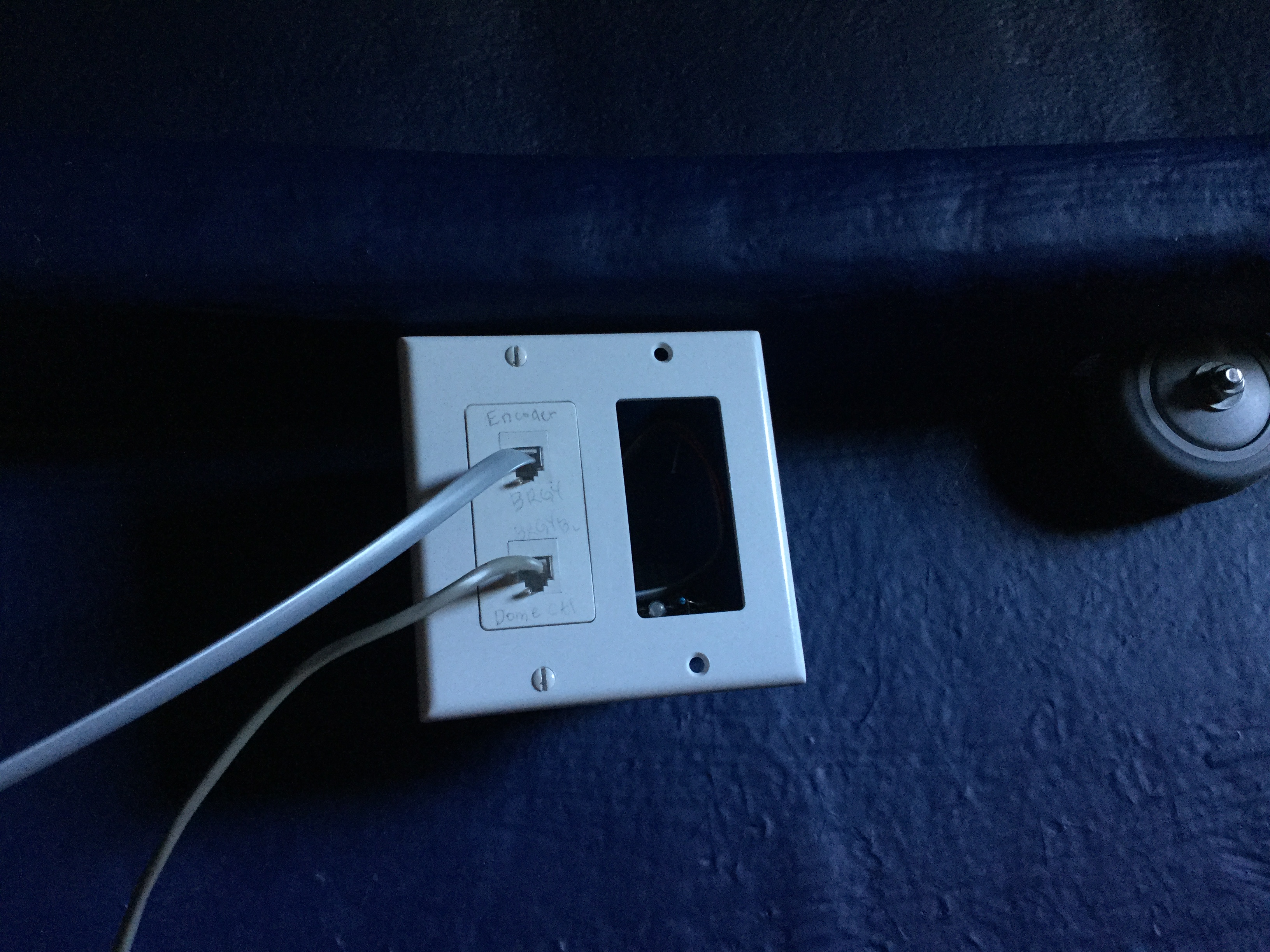
With the hardware working, I decided that having a bunch of wires hanging all over the place was not the clean installation that I was going for, so I picked up a few parts at Home Depot, and now the Home switch junction looks pretty sweet.
As I’ve been sitting in the observatory throughout the day, I’ve left the scope running, and every so often, the dome goes “ka-chunk errrrp”, as it adjusts itself to keep up with the scope. Makes me jump every time 🙂
I still need to test under the stars, but dome automation (at least the azimuth part — shutter is for later) has suddenly turned from a “hardware problem” into a “software problem”. Aw, yeah.
One thought on “Dome automation 1.0”