CNC Build, Day 34 – Assembly begins

I had been stymied by the 3/8″ bolts in the CNC build. I had trouble finding 3/8″ bolts in pan head either online or locally, so I bought socket head ones instead. This has proven to be a pain in the rear for the whole build. I was working around the tall heads, but the fact that the bolts were also lag bolts instead of all thread really sealed their fate.

I stopped by Tacoma Screw on the way home and picked up a few 3/8″-16 machine screws. I had to get flathead screw style instead of Torx or Philips, but at least they were pan head.

When I got home, I uninstalled all the bearings on the z axis table, and reinstalled them with the new bolts. This went together pretty easily, and I got the y and z bearings all installed and adjusted.

I then went to work on getting the y axis motor mount installed. That went in with minimal fuss.

I installed the router vacuum shoe next. That was a little wonky, but went on ok.

I moved to the z axis motor mount, and ran into a small snag. There is a double thickness of plywood there, so I needed longer screws. I had bought 3″ screws for just this occasion, but it turns out that I really needed 2-1/2″ instead. So I spent a little time cutting a spacer from the spare plywood I have lying around, and was just getting the holes drilled when I had to quit for the night. The spacer is going to work great, I just need to line it up with the 4 holes in the z axis motor mount seat.

In short, assembly is going pretty well. I got one idler sprocket installed, and the z table is on permanently. With any kind of time out there, I can start ripping down big parts of the assembly. There is not a lot of work before I can start installing motors and chains.

I still need to drill the holes for the x axis rails, but I decided to sort of move on and do some of the lower hanging fruit first. I will get to a point where the long rails need to happen, soon enough.

Posted in Making, Woodworking | Tagged | Leave a comment

CNC Build, day 32 and 33 – I love it when a plan comes together

My task this weekend was pretty straightforward; get the legs trimmed down, get the lower frames installed, cut and install the spacers, and install the torsion box onto the completed base.

I must say that in light of this task list, I was successful in all respects. But I’m skipping ahead.

When I left the build, I had the upper frames installed on both base pieces. I had intentionally cut the legs a little too long, with the idea that this would give the torsion box a cradle of sorts. However, they were protruding too much and I realized that they would interfere with the operation of the gantry, so they had to be cut down. I set up a fence for the tablesaw and uninstalled and reinstalled the 8 legs one at a time. I rechecked them for plumb while I reinstalled them.

I also found four pieces of wood that were all the same length (I had cut them while I was making ribs for the torsion grid), and that were the correct length to use as spacers for the lower frame. I decided that I needed at least 17″ between the frames so that I could fit the monitor down there. This leaves about a foot below the lower frame.

By the end of the first evening, I had the legs cut and the lower frame installed on the first base unit.

I knew that I had help coming on Sunday, so I needed to hurry and get as far as I could on the base unit before Anthony arrived.

I cut the four legs to size, got them reinstalled, and got the lower frame done pretty quickly. The second time is a lot easier. With the two frames built, I just needed to cut the spacers. A quick measurement, and I set up the tablesaw for the cut. I needed to make one small adjustment after testing out the first one ( luckily I needed to trim off a bit extra ), and all four spacers got created pretty quickly.

I decided where the CNC machine is going to live, and moved stuff around in the shop to clear the spot for it. In particular, I had to move the gantry construction (which has been living on sawhorses since, what, September?, somewhere else to get it out of the way. I even had time to sweep up a bit before Anthony showed up.

A short aside, the assembly of the bearings on the Z axis table is proving to be tricky. The spacing needs to be pretty exact, especially for the bolts that have two bearings on them. I found the tap and die kit, but I may have to go buy new 3/8″ bolts for this, because I don’t know how that whole thing is going together with the lag bolts I have. Back to the show.

Once Anthony was onsite, we took a short detour to see if we could get the heater running in the shop ( we couldn’t ), which made good use of the incredibly sturdy base units that were lying around but were about to become permanently stuck under a CNC. With the bases in place, we put in the spacers, checked for square, and started to work on moving the torsion box.

We went forward with the plan to put the torsion box bottom in place, then install glue, then drop the torsion box on top. This worked pretty well, but we made a couple of missteps, and I’m not certain that the bottom is really attached all that well. Nothing a few well placed nails wouldn’t fix, but I didn’t install any ( and may or may not, given how stable the whole thing is ). It’s glued in place, and shimmed in a couple of places where the box top was warping in a different direction than the bottom. The glue is curing under the weight of the box itself, which I estimate at around 250#. Once I add the plywood shelf, a spoil board, a workpiece, and the Y gantry, I estimate the whole mess will probably weigh about 600#. Needless to say, it’s not going anywhere soon.

As a coup de grace, we got the X axis rails clamped into place, all ready to be drilled and bolted when I get around to that.

With the base and the torsion box moved off of the workbench, all of a sudden, there is a lot more space in the shop again! It really felt good to get the work tables broken down and to see all that space open up.

I feel like the last huge hurdle is behind me now. I still have a pretty big task of drilling the X rails, but with them clamped in place ( and of course I have all my clamps back now they’re not keeping the torsion box level ), even that task should be easier.

I need to get the Z table straightened out. I think that I am going to just go buy some new bolts. Maybe I will see if I need some for the X axis also, although I feel pretty confident that the tolerances won’t be as tight as they are on the Y axis.

Other than those two engineering challenges, though, I think that I am nearly into full on assembly mode. Soon I hope that my complaints will be about sprockets and chains and perhaps calibration and alignment.

Thank you, Anthony, for helping out today. This part was definitely a two man job.

Posted in Making, Woodworking | Tagged , , | 1 Comment

CNC Build, day 30 and 31 — a base emerges

Last weekend, I had left myself ready to do some construction on the base for the torsion box. The CNC-cut parts are really a very small portion of the total build, although it seemed like a lot of work at the time.

In case you havent been following along, the CNC gantry (all the parts that I cut out on the Book Machine — I really need to name my CNC machines, but thats another show) moves back and forth along the X axis table, which in the case of the new machine is a bit over 4 feet wide (the bit over making it a real pain in the ass to construct from standard sheet stock) and a bit over 10 feet long (ditto). Its constructed out of 3/4 MDF (remind me next time to do it out of ply). In order to keep the table flat with the 80# gantry running over it, I built a torsion box for it to sit on, essentially a 4 high grid of MDF that resists bending and twisting. The torsion box took the better part of 3 sheets of MDF by itself, and MDF weighs about 100# per sheet, so were looking at about 400# of wood (probably closer to 700# once you add in the spoil board and workpiece) that needs to be rigidly supported, and wouldnt it be nice if it wasnt sitting on the ground, too?

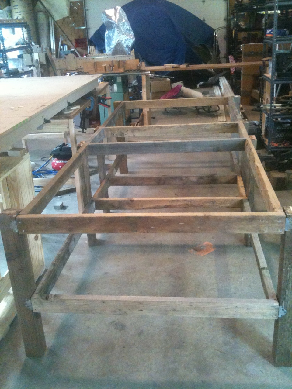
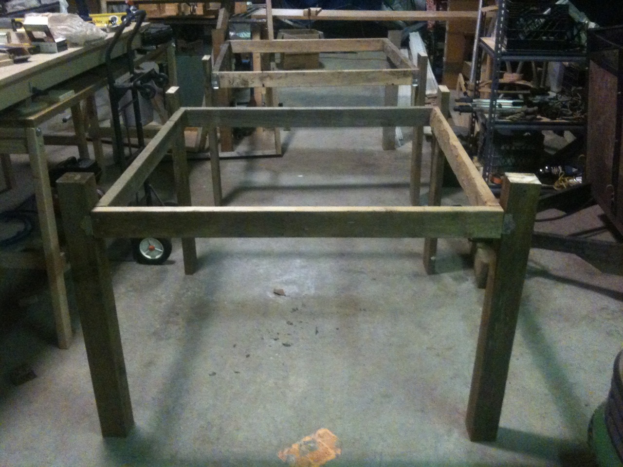
All this is to say that I needed a base for the torsion box to sit on, and it had to be tough. I already mentioned that I rummaged my scrap wood pile for parts, and the construction came together as framing made of 2×4 and legs made of a mixture of 2×6 and 4×4. Because of the way I built it, I decided that I was going to make the base have 8 legs, with the 4 corners done in 4×4 and the 4 middle legs made of 2×6.

I cut all the leg pieces as long as possible, given the wood that I had on hand, so that I left myself as flexible as possible for mounting options. Also, if I want to attach the torsion box to the base, I knew I would need some extra height on the legs to accommodate. Since Im doing design on the fly, things end up getting attached and then removed and then redesigned. Suffice it to say that this happened some during the day both yesterday and today.

By the end of the day Saturday, I had screwed and glued all four frames together, and had cut all the legs to length. My task Sunday, then, was clear; get the legs attached.

I decided that 2×6 would help to stabilize the middle joints, where I will have extra pieces to maintain the correct spacing between the frames. Attaching the 4x4s presented a challenge, but I decided to go with Simpson Strong-ties (A34 did the trick, two per leg) and that went pretty smoothly. I am on the fence about Simpson strong ties, because I am very much a screw person, and they are clearly designed for the nail type builder. Which reminds me, I need to find a real air nailer, because my brad nailer was not helping with this. Anyway, I suffered through, learning that 1-1/2 nails are a perfect size for attaching Simpson string ties to 2x4s. I am always a little unclear on the whole size of dimensional lumber and the size of nails and stuff, since they come in 1/4 increments at that size. Shrug. I have convinced myself that 1-1/4 are perfect for attaching 3/4 ply to things, and that 2-1/2 is perfect for attaching 2×4 in a butt joint.

By the end of the evening, I had two sturdy (as in, could easily support my weight on a single frame member) legged base stands.

I still need to install the lower frames (which will provide stability and also storage, once I line it with plywood – did I mention that the frame is perfectly 4 wide at the opening?), then I need to cut and install the spacers, then the bottom of the torsion box goes on ( I had an epiphany, I can maybe lay the bottom of the torsion box in the frame, put glue on it, then just drop the torsion box in place on top of it! Hmm… ). Once thats done, I move the frame to where it is going to live, and install the torsion box in it.

Once the torsion box is in situ, I can work on getting the rails installed onto it, and then I am into assembly of the new CNC machine!

There is still a bit of work to be done. Probably another 2 sessions to get the base finished, another one to get the bottom of the box installed, the frame moved into place and the box installed into the frame, then another one to do the rail installation. I would do it next weekend, but I think were out of town. Lets hope I can get this all done in February. It is going to be a photo finish.

Good work this weekend.

Posted in Making, Woodworking | Tagged , | Leave a comment

CNC Build, Day 29 – Base of scrap

I decided to spend some time working on the base for the torsion box today. I wanted to see if I could make it out of the scrap wood I have lying around.

The design I chose is a two-tiered setup — the upper frame will hold the torsion box, while the lower frame will provide stability, but also will be large enough to hold full sheet stock.

The frames are made of 2×4 lumber, while the legs are a combination of 2×6 and 4×4. Everything is stuff that came out of the yard here at Hilltop, so it feels like the house itself is giving its contribution to the CNC machine. It also feels good to reuse wood — as cheap as it is to buy new stock, there’s absolutely nothing wrong with this stuff, other than looking a little grungy. This machine will be obliterating enough wood in its time.

The day was spent hemming and hawing and measuring, followed by some quick cuts on the table saw. I had an epiphany mid-afternoon, and figured out how to incorporate a bunch of the shorter pieces I had on hand to stretch the scraps to complete the project. I would have had quite a chore trying to figure out how to use all those pieces later.

By the end of the day, I had 80% of the pieces cut for the frame, with pieces set aside for the rest, and pieces set aside for the legs. I should be able to knock it together in another long session.

I’m looking forward to having a strong base for the CNC.

Posted in Making, Woodworking | Tagged , , | Leave a comment

CNC Build, Day 28 – so happy! Together!

The CNC build has been stalled out for months. Looking back, I realize that I haven’t really touched it since Thanksgiving (2 full months and some change ago).

Thanks to John C in CA’s ingenious idea, I was able to ensure the grid was level without a lot of hassle. Anthony and I clamped temporary legs onto the grid, then leveled it to within an inch of its life, and put the MDF tops on to “relax”. That was before Christmas, I think.

Then, a couple weekends ago, I decided to put in a little time, and was able to get the Y-axis rails drilled and installed. That was satisfying. Now the Z table rolls back and forth along the Y axis.

But, mostly, the CNC just sat. Taking up a lot of room in the shop. And not getting worked on.

So today, I forced myself out there again. I really am quite close to finishing, I just need to get it over the final hump.

I spent some time getting the Z-axis rails drilled and installed. I even got 2 of the Z-axis bearings in place (although I am not certain I’m installing the bearings correctly — I’ll look into that during “assembly”). Now that those rails are on, I can complete the Z axis upper and lower assemblies, and then I’m pretty much just waiting on the torsion box.

Ah, the torsion box. I’ve spent a lot of time in the past few months wondering whether I should have just sprung for the kit. It’s sounding cheaper and cheaper as the build drags on. But I quickly realize that I would still be stuck on the torsion box. It’s just a very large object, and I need to keep it as well-built as possible, but the pieces are so large that I can’t really handle them by myself. So I have to wait for friends to drop by, and everyone has to be in the mood to do some woodworking.

When it rains, it pours, and I got two helpers today; both Anthony and Cliff showed up this afternoon! I jumped at the chance to get the torsion box top installed. We spent some time figuring out how to get the top pieces set in place (even got to rip a 2×3 down to 2″ on the tablesaw! ooo…), and pretty soon, we were ready to glue and nail the first chunk in place. With the “keystone” set, the other two pieces went on with no trouble.

The torsion box top is installed! Yes! Progress!

The glue is drying and the nails are holding everything in place.

As usual, I will sign off with the remaining punchlist:
– Torsion box bottom needs to be installed
– A base for the torsion box needs to be designed and then built
– X-axis rails need to be installed

And then we’re into assembly:
– Z-table bearings need to be installed permanently
– Motor mounts, chain mounts, sprockets, chains, axis bearings, Z drive nut, router mount clamps… I’m sure there’s stuff I’m forgetting.

I assume that building the base will be the toughest part of what’s left. It seems like the most time-consuming and measurement-heavy part of what’s left, and I’m going to try to do it with the scrap wood I have lying around, which adds an extra challenge. I figure the base should take about one session of design, measuring, and assessing the scrap pile for candidate pieces, then another session or two to cut and assemble the base. Then I need a couple friends to help get the base in place and get the torsion box set atop it.

I figured out how to clamp a jig to the drill press to make the holes in the rails come out right, although doing 10′ long rails will still pose a challenge. Shouldn’t take much total time to get that done, though. Since I’m cutting all the holes at the same time, I should be able to get this done in one long session, or maybe two.

Installing the bottom of the torsion box will be tricky — Nobody wants to flip the thing over twice, so I’m probably going to have to do it by jacking up one end or the other. We’ll see how that goes. It’s the kind of thing that I wouldn’t quit until I finished it, so that’s one should-be-quick session, might be able to squeeze in some other work into this one.

As for assembly, I don’t know of any major showstoppers right now. In theory, I could reinstall the router on the old CNC machine and re-cut any seriously offending parts. But I’m going to try to get by with what I have (with the understanding that I’m going to immediately cut out a full set of new parts on the new machine, once it’s running). Call it 3 sessions or so, but I hope that once it’s down to assembly, I’ll be motivated and happy to be making progress.

So, 4 or 5 evenings of construction, then another 2 or 3 of assembly; if I can put in some time during the week, I might be able to finish in February. If it’s weekends, I’ll be pushing it to finish before Kristi’s birthday.

I can see the finish line. I just need to keep making forward progress, and I’ll get there.

And I can’t thank Anthony and Cliff enough. Getting the torsion box top on was definitely not a 1 man job.

Posted in Making, Uncategorized, Woodworking | Tagged , , , | Leave a comment

Sugru is the new epoxy

Fashion colors, plus it loves LEGO.

LEGO + Dinosaur = Rawr!

Posted in Knowledge, Technology | Tagged , | Leave a comment

Don’t let this happen to you

The world never looks quite the same once you’ve started using Arduino.

… but you could change from “whip” to “puree” from your computer! Change speeds based on how mixed up the contents look… no, stop. 🙂

Posted in Knowledge, Science | Tagged , | Leave a comment

Sidereal Time, cont.

I’ve been looking for an electronics project, so I’ve been dredging up old shelved ones, and sidereal time made it back into my consciousness.

I posted about this last year, but decided to add some more thoughts.

First, according to Wikipedia, the length of the “tropical year” (the one most people quote as approximately 365.25 days) is 365d 5h 48m 45s (=365.2421875 days of 86400s each).

The sidereal year is one day longer.

The length of one sidereal day, then, is 86400 * (365… / 366…) = 86164.09053 seconds. This is a ratio of 1 to 1.00273790935.

If using a 32768Hz crystal (used as “clock” crystals because of their nifty interaction with 16-bit registers), then you need to instead produce 32857.715… ticks/sec instead. A whole set of calculations helps to correct the extra 89.715… ticks down to an accurate-enough algorithm.

If you want to produce 32768 ticks per sidereal second (a worthy goal; this would allow the circuit to be a drop-in replacement for the normal 32768 clock crystal), then this is the way to go.

If you want to produce a 1Hz sidereal time base, though (one tick per sidereal second), then it’s a whole different set of calculations.

If you want to do 32768 ticks/sec but the buffer you’re filling is 8-bit, that adds a bit of fun to the mix, too.

And, in the final analysis, would you rather be running the chip at 4, 8, 16, or 20MHz instead of 32kHz? Then there’s enough time to do the whole “toggle the clock circuit” plus a bunch of other work in between.

One pictures this circuit being the basis for a sidereal wall clock, but could also be used to drive a telescope mount or an orrey or… so it would be nice to use the extra processing power, since the chip has the capability anyway. I could imagine having a 1Hz output on one pin, 32kHz on another, 0.5Hz on another (for a full off-on signal in 1sec), with a stepper motor frequency (which?) on another, …

Note: Roman Black (may the sun always shine on him!) has developed a really nice way to produce very accurate timebases out of an interrupt routine on a µC This looks like a pretty straightforward way to produce the timebase I’m looking for.

Posted in Uncategorized | Leave a comment

RFID and other proximity sensing

So, I finally got the RFID kit (originally purchased at Maker Faire 2010) working. The original kit came with an RFID tag incompatible with the reader. This is why I hate buying things from MakerShed.

I am interested in experimenting with RFID, because it seems like there are a lot of uses for proximity sensors that can be identified uniquely. Turns out that the style I’m using (Mifare, 13Mhz) also have 1k of onboard EEPROM. I’m not sure how I’ll use that yet, but it seems like a promising feature. There’s some authentication understanding that I need (although I can read and write without authentication, too, to start…), and of course I need a project.

Additionally, I wired up a Hall Effect (magnetic) sensor; it lights an LED when the south pole of a magnet gets close. I’m going to use these on the CNC machine for home switches (and maybe limit switches, too — we’ll see). I have the circuit breadboarded up, I just need to build them now.

I also spent some time getting a solid understanding of “the basics”. Hooking up an LED comes pretty naturally now, but setting up an LED to work when I touch a pushbutton — yes, it’s simple, but it’s an “electronic code fragment” that I don’t really have committed to memory yet. Add to that a circuit to turn on and off an LED using a NPN transistor. As I was going through this, I figured out that the switch and 2 LEDs on the Adafruit Protoshield are not designed to work with each other (you can’t hook the switch directly to the LED; the LED needs to have its exposed pin taken HIGH (like you would from a DigitalWrite() on the Arduino, its intended purpose), and the switch drives its exposed pin LOW (like you would want for a DigitalRead() on the Arduino). One could throw in a transistor as an inverter, but that clouds the basic circuit knowledge that I was trying to gain.

So, I breadboarded up the transistor-LED-button thing from scratch, tried out a few things, couldn’t get it to work, and had to consult an online diagram to get it going. I’m not sure how much I should be experimenting on my own and how much I should be consulting references about this sort of thing. I feel like I should be able to take a datasheet and start hooking up wire to get things working, but I really am quite good at copying online schematics onto a breadboard…

Next, I’d like to play around with some ICs. 555, maybe some of the more famous amp/comparator/inverter, etc. stuff. I do want to figure out transistors, though. What’s up with PNP again?

Anyway, it’s good to be back on the breadboard again. I still need a project.

Posted in Electronics, Making | Tagged , | Leave a comment

CNC Build, Day 26 – Super-PID mods

I recently bought a Super-PID v2 to gain computer control of the router on/off. It also controls router speed, which might help my endmills last a little longer. Nice.

It has a closed-loop feedback system (it commands a certain RPM from the motor, then counts motor revolutions with a sensor, and adjusts as necessary to maintain that RPM), and the RPM sensor requires a modification to the router.

My DeWalt D26670 laminate router has no extra electronics, so it’s a pretty easy modification. I needed to pop the unit open, then paint part of the shaft white (the sensor uses light levels to determine when it’s detecting a full revolution), then mount the sensor in such a way that it detects the white area of the shaft.

The white “paint” I used was a white-ink art pen that Kristi had lying around. This was a perfect tool for the job, as it was very small and accurate and I could put the white exactly where I wanted it.

Getting the sensor mounted is a 3-step process. Step 1, I needed to mount a tube so the sensor would have a stable home. The S-PID shipped with a nice solid tube that didn’t work for me, so I cast about for a suitable alternative and landed on drinking straws. I don’t know if it will be sturdy enough, but I siliconed in a piece of straw and moved on. The next morning, the silicone was stable enough for me to work on step 2, mounting the sensor in the tube. I got the sensor placed OK, tested to make sure it was getting vastly different readings between “white” and “black” (it was full bars for white, about 1/3 bars for black, hope that’s good enough), and then more silicone to get that stuck in place.

Step 3 should be easy, but ended up being a bit tricky — putting the cover back onto the router without disturbing the sensor placement. I’d chopped a small hole in the router cover, and fed the sensor through, but when I put the router back together, suddenly the sensor wasn’t seeing the paint anymore, and I realized that it had gotten jarred loose. I went back in there, and the silicone was a total loss; I hadn’t waited long enough for it to cure. argh. So I re-siliconed, and left it to dry for the weekend. I will attempt re-assembly when I get back in town on Sunday.

I still need to figure out how to get mains power into the unit; I have a bunch of ways to get a plug attached, but not as many ways to get a receptacle. Hmm. I have really been thinking that I’d like to be able to plug/unplug things as well — I am going to work on some connectors for everything, because I hate it when I have a huge cable hanging off of something. Something along the lines of the “recessed, female” power cord outlets, like computer power supplies have. Maybe a real power outlet for the router side. And then I’d like to be able to unplug the sensor both at the router end and at the S-PID end; It’s a “standard” 3-wire connection, so I will have to think on what type of connector to use. I lean toward headphone jacks, although something with the ability to screw together could be good, maybe microphone cable. Shrug.

I will probably start by cutting the ends off an extension cord.

Posted in Electronics, Making, Woodworking | Tagged , , | Leave a comment