Sidereal seconds hand

I spent some time thrashing about trying to make sure that the circuit was producing the correct output.

I decided to try the Hz counter on my DMM, to see whether it could give me an accurate enough reading.

Hooked it all up, fired up the circuit, and…

256Hz.

Erm. Clearly I’d made an error somewhere.

I played around with the Bresenham constants, did a lot of streamlining and simplifying, and was finally able to find out that I’d set up an incorrect prescaler on the timer. With that fixed, I found:

– If I just toggle the LED every time the interrupt fires, I get ~62kHz (expect 62500 — close enough)
– If I set the Bresenham constants for add 1 and overflow at 62500, I get ~0.5Hz (half of my expected rate — fixed it by adding “2” instead for ~1.0Hz)
– If I set the Bresenham constants with a scalar that will get the numbers up close to 2^32 (4.29billion), things don’t work right.
– If I set the Bresenham constants with a scalar of 10,000 (for 32857.7158000Hz), I get ~16kHz (again, the toggling thing halves the output frequency)
– If I increase a counter by 2 every time a sidereal tick happens, and I toggle every 32857 ticks, I get ~0.999Hz

At this point, I stopped, claiming success.

This morning in the shower, I realized that I should be able to see the difference between 1Hz and 1Hz(sidereal) — they differ in the thousandths place.

So either my DMM isn’t very accurate (totally possible), or I had a code bug (very likely). I decided to blame myself, thought about where the code bug must be, and …

I’ll pause here for a second, to see if you “see” it before I did.

.
.
.

The whole point of this exercise was to get 32768Hz(sidereal) out of the circuit. That is, to produce 2^15 ticks in 1 sidereal second.

The circuit is a filter that takes a bunch of nasty numbers as input (366.24/365.24, lots more decimal places, of course, and corrected for nutation, precession, and everything else), and spits out a nice, clean 2^15 output.

So I didn’t want to toggle the pin every 32857.7158 ticks, I wanted to toggle the pin every 32768 ticks exactly.

I updated the constant, re-ran the circuit, and wouldn’t you know, my DMM now reads 1.002Hz (expected: 1.002 737 909 35). Perfect!

By the way, I was a little worried about accuracy. So I decided to check how far off my “only to 4 decimal places” time base would be against the 11 decimal places of accuracy in the number above (gleaned from the US Naval Observatory, etc).

32857.7158 / 32768 = 1.002737908935547 (the actual Hz output I expect from the circuit)

1.002 737 908 935 547 – 1.002 737 909 35 = 0.000 000 000 414 453

That’s a difference in the 10th decimal place (the 10 billionth). As I expect that the non-temperature-controlled crystal in the Arduino runs somewhere in the 20-100 parts per million error, any error from the crystal will far outshadow any derived from this calculation.

I’ll have to get the circuit onto an oscilloscope to determine how jittery the signal is. For now, though, I’m sitting here marveling at my 1Hz(sidereal) timebase!

Posted in Electronics, Knowledge, Making, Science | Tagged , , | Leave a comment

Sidereal clock, baby!

…well, I’d need an oscilloscope to confirm, of course.

But I converted the Bresenham/Black algorithm to Arduino code, mixed in code from a Timer Interrupts tutorial from the web (I should link to that here), and loaded it up.

Worked the first time. Wow. I set up pin13 to oscillate, and the Arduino’s power LED is definitely steady on, where pin 13 is definitely blinking (saw it using POV). I set the Bresenham constants to do a 1Hz blink, and the LED started blinking slow enough to see.

Bring on the stepper motors!

oooh.. I wonder if I have a convenient 16-bit counter somewhere. hmm… must think on that.

Posted in Electronics, Knowledge, Making, Science, Technology | Tagged , , , | Leave a comment

Sidereal clock circuit — progress!

I’ve been kicking around the idea of making an accurate sidereal clock circuit for years now. I’ve discussed it all before, but the basic idea is that I want to be able to create a circuit that oscillates at 32857.715Hz (32768 ticks per sidereal second).

The fact that the required frequency is irrational means that something needs to be done to correct the achieved frequency to bring it closer to the required frequency.

I played around with the idea of somehow “pushing” a 32768Hz crystal to the desired frequency — This seems like one of those “adding a lot of error” class of solutions, where what you want is to be as error-free as possible.

I also played around with (and came up with a nice algorithm for — see previous post) using a standard 32kHz crystal, but setting up a second oscillator to “add” some ticks into the normal tick stream to bring the whole system up to frequency. This could work, but it would now have 2 sources of error: the original 32kHz crystal, plus any error that was uncorrected in my algorithm.

I saw a very cool clock algorithm for Arduino made by a guy in Brazil, but his (admittedly very awesome) algorithm only works for doing 1Hz sidereal, so while I could use it to make a clock, I really wanted a 32kHz sidereal replacement, so I kept looking. I did like the idea of breaking the “float” calculation into a “decmial” one.

Then I ran across Roman Black’s treatment of the problem. He was searching for a way to synthesize 1Hz (or 100Hz) signals out of random source crystals, and utilized Bresenham’s Line Algorithm in a very nifty way. Essentially, you maintain a counter, and when it passes a limit, you subtract that limit, but leave the remainder in the counter. Thus, all required ticks are accounted for, and the output frequency is “eventually consistent”.

I realized as soon as I saw this method that it would be perfect for what I was trying to do. I just needed to figure out how to set up the algorithm to produce the necessary ticks.

I checked my nearest Arduino, and found that it’s running a 16MHz crystal. Also, unlike PIC, Atmel chips don’t have a 4-cycle instruction set, so the chip really puts out 16 million instructions per second (one every 0.0625µS!).

To drive the algorithm, I needed 4 variables:
A – target_ticks – frequency in Hz of the output oscillation
B – cpu_ticks – frequency in Hz of CPU oscillation
C – timer_ticks – how many cpu_ticks before the timer overflows
D – bresenham_scalar – more on this in a second.

From these you synthesize:
E = B/C – max_ticks – number of timer overflows in 1 second

In my case, I needed:
A = 32857.715…
B = 16,000,000
C = 256 (8-bit Timer2 — won’t need tone() out of the Arduino for this)

The idea is:
Set up the timer to interrupt on overflow.
When it overflows, add target_ticks to the tick count.
Then check whether the tick count has exceeded max_ticks, and if it has:
– subtract max_ticks from the tick count
– toggle the output pin

… and that’s it. The pin will toggle whenever the tick count gets high enough, the remaining ticks will stay “in play”, and the output will be toggled the correct number of times (on average, over time).

In order to make the interrupt routine run as fast as possible, we want to store ticks as a 32-bit integer. Because the target_ticks is an irrational number (being a ratio of two irrational numbers), it would be nice to get some extra accuracy in the form of pulling out some decimal places of accuracy out of the irrational target frequency.

As a first pass, I just multiplied the target frequency and the max frequency by some multiple of 10, keeping both numbers less than 2^32 (the max size of a 32-bit int). However, that ended up leaving some accuracy on the table, because the max frequency can be scaled by more than 10^4 but less than 10^5 before overflowing maxint. So, we can pull a little extra accuracy out of the timer by choosing a scalar more carefully.

The choice of scalar is highly dependent upon all the variables (an 8MHz CPU cannot use a full 8-bit timer overflow for this — there are only 31250 overflows/sec but a required frequency of 32857… so you need to overflow faster, or otherwise synthesize a faster clock). But for the 16MHz/8-bit/32kHz target frequency, a scalar of 68,700 will pull 4.8 decimal places of accuracy out of the timer, as opposed to 4 decimal places with a 10,000 scalar. For a bunch of precalculated values, this is not a big loss of readability.

So I wrote myself up a little Python script to test my configuration; it didn’t wait for timer overflows; it just ran in a while loop and cranked out info. Here’s what I got, after a simulated 10,000 second (2.7 hour) run:

Output ticks Timer Overflows Remainder
325948540 620000000 1.66
326277118 620625000 0.05
326605695 621250000 0.36
326934272 621875000 0.66
327262849 622500000 0.96
327591426 623125000 1.26
327920003 623750000 1.56
328248580 624375000 1.86
328577158 625000000 0.26

Notes:
These are 10-second intervals (62500 * 10 overflows between each)
At 10,000 seconds (62500 * 10000), the number of output ticks is accurate to all 4 decimal places (328577158 ticks = 32857.7158Hz for 10000 seconds)
At each of the snapshotted time segments, the remainder flows between close to 0 (a tiny bit extra left in the counter) and close to 2 (almost but not quite enough to overflow). There is jitter, but over time, the algorithm puts out the correct number of ticks.

In short, the Python script works perfectly.

Now I just need to translate it to Arduino, and then I can decide what to do with my newfound sidereal time base!

edit: I created an Arduino sketch for this, and have also included the Python script, for reference.

Posted in Computers, Electronics, Knowledge, Making, Science, Technology | Tagged , , , | 3 Comments

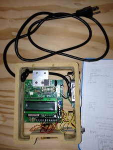
CNC – SuperPID installed into case

I knew that I was getting pretty close to being done with the Super-PID installation.

I had a bunch of cable connections to make, and the board was pretty much ready to install into its new case.

I decided to deal with the 3 exposed G540 ports (input 1 for home switches, inputs 2 and 3 currently unused but broken out in the DB-9) first. I crimped on some servo pins, added a (female) servo connector, messed around with it until everything fit, and that was that.

Next, I put together a servo connector for the power and ground wires. These are coming directly from the PC power supply, and will be supplying power to all the 5v circuitry in the Super-PID, as well as the home switches (and eventually whatever else I add to the other inputs). One pin was empty, of course, but servo connectors are so easy to use that I like the idea of standardizing on them where possible.

Then I made 3 cables that terminated in bare wire at one end (for 2 different power connections on the Super-PID, and for the SL and SO on the RPM sensor) and servo connectors on the other.

With all the cable terminations done, I was ready to start hooking everything up. I attached the 110v stuff carefully, hooking the mains input to the Super-PID and the mains ground to the ground on the outlet. Then I hooked the Super-PID 110v output to the AC outlet. I taped the outlet’s side studs, as they will not be completely inaccessible the way the case is set up.

Then I hooked the DB-9 power, 2 power sources on the S-PID, G540 inputs cable, RUN, TACH, and POT wires from the DB-9 and the RPM sensor connection (inside the case). Things look a little bit messy, but the cables are all hooked up, and the Super-PID is almost ready to test!

20130106_CNC_SuperPID_soldered

Next steps:
– put a servo connector on the RPM sensor cable
– make a “back” for the S-PID case (for the Super-PID and the perfboard to bolt to)
– make a “front” for the S-PID case (either clear or with a hole for the LCD
– Bolt the whole thing to the CNC machine.

And suddenly I will have router speed control!

I may decide to hook up the potentiometer and a SPDT switch to allow me to switch from computer control to manual control of the speed. I can make that decision when I build the front of the case.

I could potentially also hook switches to the “RUN” pin for:
– being able to turn off the router manually
– driving a 5v/120vac relay to turn the vacuum on and off

but that’s for another day.

Today, I’m happy that I’m very, very close to finally getting the S-PID installed. It’s been sitting around for over a year now.

Posted in Electronics, Making | Tagged , | Leave a comment

CNC – SuperPID case work

I finally got back to the case for the Super-PID. When I last left the build, I’d finished wiring up the G540 and had put the PC back together.

At this point, I needed to start getting serious about getting the case put together. I had to do a little chisel work to cut out the holes for the AC outlet and DB-9 port.

With that complete, I started gluing the case together. I did it in 2 sections to make sure that everything lined up as well as I could make it.

While the glue was drying, I started scratching my head about how to hook up the DB-9, perfboard, and Super-PID all together. There are a lot of wires in there, and so it took a bit of head-scratching to remember where I had left off, and get everything laid out.

The perfboard is set up so that half of it is inside the case (with the Super-PID) and half of it is outside the case (to provide an interface to the home switches and Super-PID RPM sensor). I’m no perfboard expert — the back side of my builds always looks like a mess — but I eventually got it all put together. There’s a nice big power rail with extra spots to provide power and ground to various accessories (I might need some more of these later, who knows?), and I have the 3 accessible pins from the DB-9 (inputs 2 and 3 to the G540 which are currently unused, and the home switch which is on G540 output 1) broken out. I also broke out the LED and Output from the RPM Sensor — I’m pretty sure that I could have just hooked the LED pin to +5v, but I exposed it just in case. Externally, I made 3 “servo” style connections (albeit +5v,0v,Output to match the Hall Effect chip) for the home switches, and a second “servo” style connection (a more standard 0v,+5v,Output) for the RPM Sensor.

That was quite a bit of soldering, but once it was done, I realized that I was pretty much done with the build! All that was left was to start making the actual connections.

I also installed the AC outlet and DB-9 and the AC plug cable.

The Super-PID case is really starting to come together — I think that with a few crimped ends, I might be ready to roll!

Posted in Electronics, Making, Woodworking | Tagged , | Leave a comment

A slice of Pi

I have a Raspberry Pi on the way.

Since I’m mostly an Arduino shop, I have to think about how to interface my existing goodies with the new board.

This one looks cool:R Pi to Arduino Shields

It makes use of an XBee footprint to allow lots of other sensors. The same company sells them, but here’s the place I first saw that sort of thing:

Seeeed Studio

Also, although I will probably use mostly SSH to connect to my RasPi, it’s also possible to use the Raspberry Pi as a “laptop” (monitor and keyboard); it looks like you can pick up a smartphone dock and do some creative cable management: RasPi laptop

Watch this space as I gather more Raspberry Pi info.

Posted in Computers, Knowledge, Technology | Tagged , , | Leave a comment

Bringing the Home Theater together with Plex

I tried XBMC as a Home Theater PC “OS” — it certainly did a fine job of presenting movies from our LAN in an easy-to-navigate manner. But, because Netflix was on another box, and Tivo on yet another, the HTPC didn’t get used as much as I’d like.

Also, the movie list gets stale pretty quickly, and the workflow for getting new movies in (which is a very manual process involving Mac the Ripper and Handbrake) is tedious enough that I am not getting it done as quickly as I’d like.

I can’t fix the ripping process — it’s a pain no matter how you slice it.

But getting all the rest of the media onto the HTPC turns out to be a snap.

Enter Plex.

Plex was originally a branch of XBMC (which has a long and storied history, worth reading), but has had so much development done in the branch that it’s now a package on its own.

Plex is built around a very simple two-tiered structure; Plex Media Server runs on a single machine, and feeds files to one or more Plex Clients (which are available for Mac, iOS, etc). This makes for a very flexible system, and when we switched from XBMC to Plex, suddenly every screen in the house is a potential TV. Nice!

It’s also free (as in beer), except for the iOS app (which runs on both phone and pad) for $5. Normally, I don’t buy a whole lot of apps, but this one is Totally Worth It. In addition to being able to stream media from the Plex Server (want to watch a show while brushing your teeth? no problem), the iOS app can also be used as a remote control for the Plex Client running on the TV! Watch a show on the phone, pause it, push it to the TV, use the phone as a remote, it picks up where you paused it, take it back to a pad — you get the idea. It is very, very slick.

And, with the addition of myPlex, you can even stream media to devices that are not on the LAN! Being out in the biomass, kids watching a movie in the car… the possibilities are endless.

And Plex is designed as an app framework. So, there’s a Netflix app, a Hulu app, and dozens of others. What that means is that you can boot your HTPC into Plex and then never have to leave the app. It’s what the Tivo really wanted to be, except that it does Movies, Netflix, and other media (Plex can scrape iTunes and iPhoto, too) as well.

Plex is about to become the only thing hooked to the TV in the living room. The XBox goes back to being a game machine, and all the other video media gets done on the HTPC.

It’s a whole new thing. And I like it.

Posted in Computers, Knowledge, Technology | Tagged , , , | Leave a comment

EyeTV is the new Tivo

I’m in the process of updating/rebooting my home theater. The most complicated part of this is the Tivo/Live TV replacement.

I considered trying Hulu, but because I already have a HD-ready off-air antenna, I decided to see whether I could use that.

After some research, I picked up a HD HomeRun, which is a device that takes the OTA antenna signal and drops it onto the LAN. $88 on Amazon, one time fee.

To read those signals, I picked up Elgato’s EyeTV software, which essentially does the job of a Tivo (takes program guide information, allows user to schedule shows for recording, records the shows to disk). EyeTV is $79; it uses TVGuide.com’s Electronic Program Guide, which costs $20/year, first year is free.

So, for a startup cost of about $175, I now have TV shows recording automatically again.

And now, believe it or not, is where it actually starts getting complicated.

EyeTV produces shows packaged as .eyetv files. These files are little bundles that include; one or more video files containing the show itself, along with a few “metadata” files that contain things like the show’s title, air date, channel and assorted other stuff.

The .eyetv files are named things like:

Cheers – Where Everybody Knows Your Name.eyetv

But XBMC (or other home theater OS software — that’s another show) want to see TV shows named like this:

TV Shows/Cheers/Season 1/Cheers.S01E01 – Where Everybody Knows Your Name.mpg

So, the .eyetv file needs to be cracked open, and the metadata (which is in XML) needs to be parsed out to construct this new name.

Some poking around with Python produced a script to perform that task, and some additional Googling revealed a way to automatically fire off the Python script anytime a new .eyetv file shows up.

That gets us about 90% of the way there; honestly, that’s as far as Tivo had gotten. That is, the shows are now in the correct folder, and the HTPC can read them, but they still have commercials in them.

Various kind souls on the ‘net have figured out how to strip commercials from shows, and, if there is going to be a further upgrade to the new Tivo system, this will be it. Here’s an article about commercial skipping in EyeTV files (search for the post with the word “mp4chaps” in it).

Someday, we’ll start running into disk space problems, as there’s no auto-culling of shows. But, since the shows are broken out by show and season, it should be fairly straightforward to fix that later.

A final note: among other things I’ve figured out in this process, I discovered that we receive a total of 40 off-air channels at our house. Forty. There are at least 2 channels that show nothing but movies! In a word, w00t.

Posted in Computers, Knowledge, Technology | Tagged , , | Leave a comment

Tivo – The Big TV Reboot

I’ve been increasingly dissatisfied with my home theater setup.

Primarily, the home theater is designed around the TV and a 5.1 Dolby Digital audio system, so it’s tuned for movies and TV shows and videogames (to a much lesser extent music and photos and web surfing).

In the most recent iteration (which has been crumbling slowly as I’ve lost the will to maintain it), I had:
– Tivo (primary source of TV, mostly recorded, but some live)
– Netflix (running on the XBox 360, for TV and Movies)
– DVDs (embodied in 3 DVD jukeboxes, which should have been the primary source of movies, but which was too brittle to be real useful)
– Mac Mini (10.5, 1gb, 2.0Ghz Core 2 Duo) running XBMC (to which I was slowly ripping the DVDs)

To run this, we pay for DirecTV (~$70/mo) and Netflix streaming (~$10/mo).

And when we want to watch a particular show, we have to search several places for it.

When I approached the problem of shutting off DirecTV a couple years ago, I was stymied by 3 hard requirements:
– lack of children’s TV on Netflix
– we watched a handful of shows on “cable” channels (SciFi, Food Net, etc)
– we would still “channel surf” live TV occasionally

In the intervening years, all three of these requirements were mitigated, and we also acquired a free OTA antenna (thanks, Anthony!).

Still, nothing was going to change until something went awry; that happened last week, when the Tivo finally started giving up the ghost.

I sprung into action.

Posted in Computers, Knowledge, Technology | Tagged , , , | Leave a comment

CNC, another satisfied customer

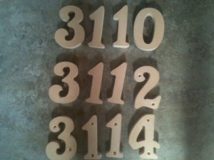
My Mom asked me to cut new house numbers for her triplex. A couple of the old numbers got broken when she had the house painted last summer.

After a bit of negotiation, we agreed that it would be difficult for me to match the existing numbers, so I sent her some font samples, she picked one, and then I set up to cut out the numbers for all 3 units.

I think they came out pretty nice:

The cut helped me to work out some kinks in the system. Here are a few challenges I had to overcome.

First, The Y axis needs a new rail; the little extra bit at the end is not working. I found that out cutting the Super-pid case, so I moved the cut space to avoid that spot for the numbers cut.

Then, I really need to work on attaching the DB-9s in the motor connectors more securely. I ruined a bunch of wood when the Y axis motor kept coming loose. I decided, for now, to tape the connectors with painter’s tape.

Once I got that working again, the drive sprocket from the Y axis popped off; I need to get that fixed with Loctite (and I generally need to Loctite all the moving parts).

Once I got all the minor repairs done, I remembered the hard way that I need to work on hold-down screws — I lost one number and gouged a couple more before I fixed that problem.

The router is really starting to sound bad. I think it’s about to die. I’m saving up for a Porter Cable 890 anyway, but it just makes me think about how much cutting that tool has done. And maybe about whether I’m cooling it properly.

In addition to troubleshooting, I learned some stuff about my workflow.

First, “Engrave” in CamBam goes “on the line”, where “Profile” “leaves the line”, either to the inside or the outside. That’s cool. However, If you are using this to then cut all the way through the geometry (by Engraving to -0.75″), the toolpath does a “LevelFirst” cut (taking out all the 1/8″ stuff, then moving to do each letter at 1/4″, …) instead of a “DepthFirst” cut (cutting out each letter before moving to the next). This actually helped me when I decided to stop the machine after the 1/8″ pass to put in hold-down screws, but it would be nice to have the machine do that a little more automatically; I really had to chase the endmill.

Also, I used the SketchUp-to-CamBam plugin, and it works great! I think SketchUp is my new modeling tool. I spent some time working on the art for the Halloween decorations, and SketchUp made it really easy to trace an existing bitmap.

Finally, I am liking the vacuum shoe more and more. The bit still throws a little sawdust around, but most of the dust just sits on the table, waiting for me to come through and vacuum it up. I kind of want an additional hose (or to have a hose that sucks up the sawdust as it runs), but for now this is a big improvement over getting sawdust actively blown all over creation.

I really feel like I’m rolling with the CNC now. I have made a lot of progress on projects. If I could get the Super-PID installed, I think I’d feel pretty confident that the machine is going to cut about anything that I throw at it.

Posted in Making, Woodworking | Tagged , , , | Leave a comment