CNC software – designing Cerberus

CNC software is a three-headed beast (hence “Cerberus”).

To go from “idea” to “cut piece”, you need:

– CAD software, to build the 3D model of the object (or the “2.5D” layout, or the 2D circuit diagram or whatever);
– CAM software, which takes the model and turns it into G-code; and
– Control software, which turns G-code into step-and-direction pulses out the PC’s communication port

Since there is a file created in between each of these steps (DXF for the CAD->CAM, G-code for the CAM->Control), they can be performed on the same machine or different ones, depending on the use case.

In order to make life easier, and also to get the user locked in to a particular company’s software, some or all of these functions are sometimes made by the same company.

Prices range from “hobbyist” (free to <$200), through "small shop" (<$2000) and on up. AutoCAD and SolidWorks are agreed to be the "serious" software suites. I didn't even bother looking up prices, because every so often I run across something that's $15K/seat and I just chuckle. All of these software packages have fans and detractors, who get bunched panties about their side of the story, nothing out of the ordinary there. I will talk about the ones I think I'll be using, in no particular order, just the order I discovered them. ArtSoft's Mach3 seems to be the de-facto hobbyist standard control package. All the hardware vendors supply Mach3 plugins, and generally everyone just assumes this is what you are using. The "trial" version is only slightly crippled in that it will only do G-code files up to 500 lines. Not really understanding G-code, I wonder how crippling this really is. In fact, I wonder if I could figure out a way to break a large G-code file into 500-line chunks programatically... but that's another show. Anyway, the paid version costs $150 or so (I've seen deals at $140, so shop around), and has a 10M line limit. That is probably enough to do almost anything a hobbyist could want. For CAD, it often depends upon what you're trying to output. For circuit boards, Eagle gets used. For 2.5D (maybe 3D), Alibre seems popular. Alibre is $99, with a "my trial expired but I haven't paid yet" version that is somewhat crippled (but I'm not sure how). Anything that can be used to create a 3D model can be used for this step; 3D Studio Max, Rhino, ... so I will have to see what package works best. I will probably end up going with Alibre. OK. So I have the ability to drive the machine, and I have the ability to make the models. I just need something to convert models into toolpaths. It should be easy to find a good CAM program, right? Wrong. At the moment, I have found the following sort-of-free CAM programs: CAMBam, Artsoft LazyCAM (Mach3 guys), MecSoft FreeMill (same as VisualMill guys?). There are others whose names come up a lot. The thing that scares me about this is that it seems like either the CAM programs are free, or they cost $1000. There is no middle ground. I'm not entirely certain what that's about. So for $250, I could have a whole 3-headed workflow engine going ($150 for Mach3 and $100 for Alibre, and some free CAM). If I can use Rhino or 3DS Max, I can save myself some $ there. ...and I'm not sure I have a full handle on it all. But there you go. CNC software as I see it.

Posted in Electronics, Making | Tagged | Leave a comment

CNC plans on hold

I will continue researching CNC software and firmware, maybe build out my CNC Etch-a-Sketch like I’d been wanting to. I don’t know if the Ladyada Motor shield can juice the motors up enough to drive the EaS, but I can try.

If I can get the CNC EaS built, then get it connected to Mach3 or otherwise translating G-code into a pulse train, I think I’ll be ready once I pull the trigger on the “real” CNC project.

Posted in Electronics, Making | Tagged , | Leave a comment

CNC – Electronics

The electronics for a CNC machine are reasonably complicated, and consist of:

– 3 motors, one per axis, which drive the leadscrews that position the axes, driven by
– 3 “motor drivers”, one per motor; the boards convert TTL-level “step” and “direction” signals into high-power coil energizations in the motors. Each board connects to
– one high-voltage (24v, 36v, 48v, 60v) DC power supply that supplies the big current and voltages that the motors require, and
– one “breakout board”, which turns signal pulses from the PC into 3 clean TTL-level pulse trains feeding each of the 3 motor drivers. The breakout board connects to the PC via either DB25 parallel (most common) or USB (harder to find), and sometimes has additional features, like being able to turn on and off the “spindle” (cutting tool), and sometimes requires its own 5vDC power supply.

All of the above (except the motors, which are connected directly to the machine axes) can be put into a single enclosure “black box” that plugs into an AC outlet, and provides motor outputs and PC input (as well as an Emergency-Stop switch, home and limit switch connectors, spindle control connector, etc.)

The full constellation of PC software is out of the scope of this article, but the “machine end” of that software train is a piece of software that translates “G-Code”, a specialized CNC cutting language, into a series of “step” and “direction” pulses that get sent to the motors via the electronics “black box”. One such piece of software (and what seems to be the DIY “industry” standard) is called Mach3. More on this in the “software” section.

For a low-cost DIY CNC machine with a total budget of perhaps $800 (assuming that the PC and its software are not part of this cost), the choice of electronics is critical, encompassing about $500-$600 of that budget. The fasteners and wood are cheap, comparatively.

One can spend a lot of time building the black box out and coming at it from various directions, but at the end of the day, the main two choices are these:
– How big must the motors be in order to drive the machine-as-designed, and
– What is the upgrade path for the electronics

There is a tendency to want to size everything “just a little big” to keep a possibly larger future upgrade path in mind. I feel that avoiding this tendency is a good idea, especially considering I don’t really have a good feel for the capability gained by incremental capacity improvements in the electronics.

Having said that, my choice boils down to essentially two options:

Option 1 “Right-size it”:
For $390, buildyourCNC sells 3x 387oz/in steppers, 3x 40v@3A drivers, a 36v/8.8A power supply, and a DB25 BOB. He’s sized this set to drive the rig in his plans. I don’t have a feel for how much “extra” capacity there is, but I have a feeling that he’d have a worse reputation on the ‘net if he’d severely undersized anything. I do get the idea that adding a second motor and driver in X (for an additional $100) is often helpful — my understanding is that the machine is not lightweight. For an extra $200, I can get an enclosure, E-stop, and all the connectors wired in already ($429 + $150 in motors from kelinginc).

Option 2 “Build for the future”
For $520, kelinginc sells 3x 387 oz/in steppers, a Geckodrive G540 4-drivers-and-a-BOB, and a 36v/8.8A power supply. The G540 will handle motors up to 50v/3.5A, has a 4th axis in case I need to beef up X, and is the industry standard stepper driver. I don’t know that I get a whole lot of “extra expansion” out of the Gecko, but certainly I can count on it.

There are larger motors (NEMA 34 and 42), larger drivers (60v/5A), larger power supplies (you get the idea). I am fairly certain I don’t want to underbuild. But overbuilding doesn’t feel right, either. I don’t know what I’m doing yet.

About the enclosure. I like the idea that I have a relatively dust-free and “throw the switch” solution. OTOH, I wonder if building an enclosure will seem like such a big deal when I have a CNC machine sitting around…

Posted in Electronics, Making | Tagged | Leave a comment

CNC – design ideas

After much research, I have decided that I should aim to build a moving-gantry, 3-axis mill, with a 2′ x 4′ bed (sized for a 1/4 sheet of plywood, although I will only be able to use about 20″x40″ of that as cuttable area).

There are several sets of plans for machines online:
buildyourcnc.com
DIYLILCNC.com
JGRO
Joe’s

… I have decided to build against the buildyourcnc plans.

The infrastructure will be of 3/4″ hardwood ply, with NEMA-23 size stepper motors. The rest of the electronics kit is TBD.

Posted in Electronics, Making | Tagged | Leave a comment

DIY CNC – A Mathematically Constrained Robot

Ah, CNC. The promise of turning idea into creation.

The idea of owning a CNC machine appeals to me on many levels.

I often have project ideas that I can’t figure out how to construct because of my limited toolset or skill with the tools I own.

Being able to accurately cut and drill wood and PCB opens the possibility of many nifty contraptions.

I have been trying to figure out motors in general and steppers in particular for quite some time.

Like mirror grinding, I like the idea of something that can be made with rough hand tools, but produce a precision result.

And of course there are very few objects that require a true renaissance man constellation of disciplines: woodwork, engineering, electronics, drafting, and art. Mediums include wood, metal, electricity, hardware, firmware, software, and infrastructure. Translations from thought to drawing to G-code to a pulse train to physical movement to a cut piece… it feels like the very essence of what it is to be a Maker.

I will attempt to figure out how to create this, my golden plow.

Posted in Electronics, Making | Tagged | Leave a comment

Sidereal time

The stars rise about 4 minutes earlier every day, making them seem to march ever-westward across the sky.

I received the gift of a real-time clock (RTC) circuit last week, and it got me to thinking about how to convert a RTC tuned to solar time into one tuned to sidereal time.
Continue reading

Posted in Electronics, Knowledge, Science, Technology | Tagged , | 1 Comment

RFID Reader kit, redux

My last build of the RFID kit was a little messy, so I decided to re-wire it from scratch on a clean breadboard.
Continue reading

Posted in Electronics | 2 Comments

RFID Reader Kit

I have been wanting to learn RFID lately, so I picked up an Arduino-based RFID reader/writer kit while at Maker Faire last month.

I built the kit according to the photos I found on the author’s (is a kit maker called an author?) website.

At the moment, I’m having some trouble getting the kit up and running.
Continue reading

Posted in Electronics | 1 Comment

Temperature Differential sensor

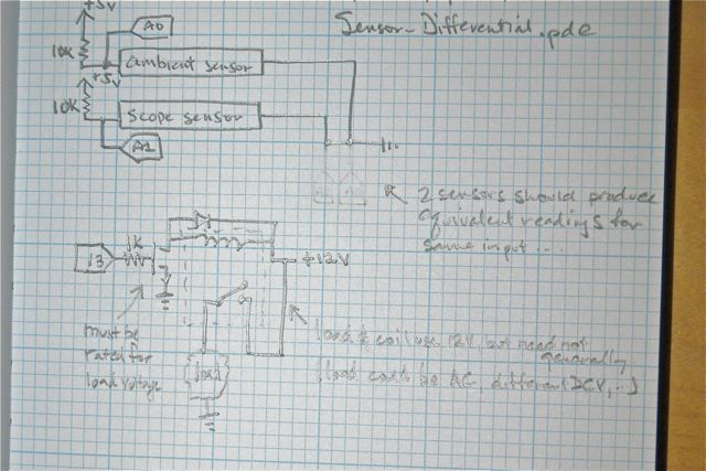
I plan to construct an Arduino circuit which will read two temperature sensors, and turn on a relay if the differential gets too large.

This is eventually to be pressed into service on the dew heaters for the telescope.

But for now, I rigged up a nice little circuit which turns on a relay based on input from two light sensors.

Circuit Diagram:

Here is the Arduino sketch. The two sensors are on A0 and A1. The relay trigger pin is 13.

I am using a 12v relay, so I am powering the Arduino from a regulated 13.8v supply. I am using the same supply voltage to drive the relay. To amplify the Arduino’s digital output to a level useful to the relay, I am using a N-type MOSFET. I have a diode wired “backwards” across the relay coil to prevent voltage spikes when the relay shuts off.

Posted in Electronics, Making | Tagged , , | Leave a comment

Robotics competition

I volunteered at the US FIRST Robotics competition last weekend. High school teams have 6 weeks to design and build a robot from a given kit of parts, the robots then play a game determined by FIRST; this year was soccer.

It was realyl fun to see these bright-eyed and enthusiastic young scholars. I mean, you know they can’t be the most popular people in school, but they really put together some complicated builds, and I was gratified to see a number of girls competing among the teams, too.

Makes me want to break out the soldering iron again. Not that I have a project in mind.

Posted in Uncategorized | Leave a comment